Introduction
SnapModbus is an Open-Source multi-platform suite (library and tools) to manage Modbus communication in strict adherence to the modbus.org specifications, both master and slave side. It supports all the functions described in the documents:
- MODBUS APPLICATION PROTOCOL SPECIFICATION V1.1b3
- MODBUS MESSAGING ON TCP/IP IMPLEMENTATION GUIDE V1.0b
- MODBUS over Serial Line - Specification and Implementation Guide V1.02
through the standard transport protocols and the most widespread unofficial protocols.
It’s released under lglp v3, so it’s free also for commercial use.
Why SnapModbus ?
The Modbus protocol has been consolidated for many years of use, there are millions of devices in the world that implement it and, given that it is a protocol with public and well documented specifications, there are dozens of excellent libraries that implement it, both free and commercial.
So, the question is: did we need any more libraries? How are they different?
The main purpose of this suite is to greatly simplify the commissioning of a Modbus system, Generally, the communication libraries focus only on the way of transferring data to and from the peripheral, limiting themselves to the syntax and showing an "educational" aspect where all the devices are homogeneous.
The reality is quite different, we often find ourselves faced with a "field" made up of various peripherals of different technology (Ethernet or serial) which have different response times and whose data need to be updated with different methods and times. The challenging work is not how to exchange data with one device, but how to exchange data with all of them efficiently.
SnapMB's goal (which I hope it has achieved) is to manage a complex field as easily and efficiently as possible. This through the abstraction of the transfer protocol (a TCP or RTU client are the same object and its behavior can be changed on the fly) and the availability of two architecture models:
- Virtual Bus
a protocol-independent half-duplex way to communicate with all devices, regardless of their technology (Ethernet or Serial). - Fully parallel management
a multithreaded way to peer-to-peer data exchange with all devices (including RTU devices) simultaneously.
Many wrappers (library interfaces) and examples for the main high-level programming languages are provided, only a basic knowledge of your own programming language is required.
For an "instant use", in the distribution, are already present the compiled tools and the binary libraries for the OS which don't have c++ compiler by default.
Info
In accordance with the latest trend of fairness and inclusion, some key terms have been changed. Master and Slave become Controller (or Client) and Device; Blacklist and Whitelist become Blocklist and Allowlist. You will find this terminology both in the documentation and in the source code. It's a small mental effort against a great cultural advantage, so thanks for your patience.
Highlights
- Complete adherence to Modbus specifications and complete implementation of functions
- Can read up to 65535 registers/bit with a single call.
The Client automatically splits calls when the number of elements is greater than allowed by the protocol. - Fully thread-safe
Allows the creation of multiple Devices (with different IP/Port) working with same shared areas. See here - Optimized procedures for serial management
- Smart Connect
During the TCP connection, a ping is performed first to avoid the TCP timeout. - Intelligent timeout management
Since in Modbus protocol, a "non answer" is itself an answer, it's important to set a correct timeout. SnapMB allows self-learning of the response times of each device and can automatically set the timeout to double the average times. - Data consistency is always guaranteed both at the device and application level (see here)
- Advanced debugging and raw transfer functions that allow the experimentation and implementation of particular software using few lines of code (gateways or protocol converters)
- 20 parameters allow fine tuning.
Specifications
| Environment | |
|---|---|
| Architecture | Native Intel/ARM - 32/64 bit |
| Supported OS |
|
| Datalink |
|
| Transport protocols |
|
| Modbus Functions | All listed into MODBUS APPLICATION PROTOCOL SPECIFICATION V1.1b3 |
Note
UDP, RTU Over TCP and RTU Over UDP are not officially supported by Modbus specifications
Test platforms used
| OS/Version | Toolchain used | OS Model | App Tested |
|---|---|---|---|
| Windows 7 Pro | Visual Studio/MinGW (*) | Win64 | 32/64 bit |
| Windows 10 Pro | Visual Studio/MinGW (*) | Win64 | 32/64 bit |
| Windows 11 Pro | Visual Studio/MinGW (*) | Win64 | 32/64 bit |
| Linux (Intel) Mint 21.00 (5.15.0-43) | g++ 11.3.0 | x86_64 | 64 bit |
| Linux (Intel) Ubuntu 21.10 | g++ 11.2.0 | x86_64 | 64 bit |
| Linux (ARM) Raspbian 32 bit | g++ 10.2.1 | arm32 | 32 bit |
| Linux (ARM) Raspberry OS | g++ 10.2.1 | aarch64 | 64 bit |
| FreeBSD (Intel) 13.1 | g++ 11.3.0 | amd64 | 64 bit |
| macOS (Intel) Catalina | g++ (clang 14.0.0) | x86_64 | 64 bit |
| macOS (Intel) Monterey | g++ (clang 14.0.0) | x86_64 | 64 bit |
| macOS (Intel) Ventura | g++ (clang 14.0.0) | x86_64 | 64 bit |
| macOS (Apple M2) Monterey | g++ (clang 14.0.0) | arm64 | 64 bit |
| macOS (Apple M2) Ventura | g++ (clang 14.0.0) | arm64 | 64 bit |
(*) Visual Studio 2022 Community Edition / TDM GCC 64 (g++ 10.3.0)
Architecture
In SnapModbus there are three Objects
The Field Controller and the Client, aka Masters, which are the active actors, they manage the communication querying the peripherals.
- The Field Controller manages the whole Field in Half-Duplex way.
- The clients are peer-to-peer, each of them can manage only one device but they do it independently, that is, in a multithreaded architecture they can work in parallel.
The Device, aka Slave, which is the passive actor, it serves the queries that came from the active actor.
Note
The Field is a virtual Bus, i.e., a set of heterogeneous peripherals: RS232/485 with different speeds and formats (RTU or ASCII) and Ethernet, which are managed by the same Controller. The physical bus, on the other hand, provides that all the peripherals are homogeneous, i.e., this happens with Modbus RTU/ASCII.
Client/Controller
Using the Field Controller
The Field Controller works in Half-Duplex mode, i.e. it exchanges data with one Device at a time in a sequential manner. Send the request, wait for the response and, only then, can move on to the next Device. Half-duplex management is not the most efficient, but the great advantage of the Field Controller is that of managing all the Devices present, of whatever type they are.
To use the Field Controller three steps are needed:
- List of Devices and definition of hardware resources.
- Standardization of addresses (Device ID)
- Creation of the controller and device descriptors.
Let's look at a practical case study.
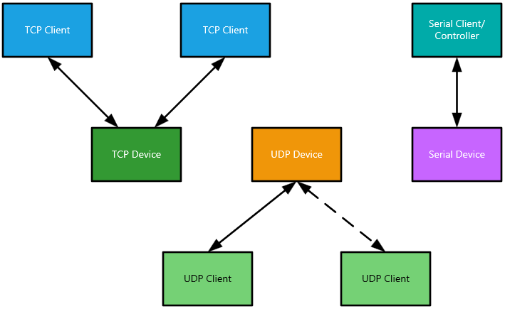
Suppose we have a set of Devices to manage as in the figure.
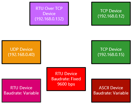
As we can see, they are very different from each other.
Ethernet Devices are of little concern to us because, even if they have different transport protocols, from a hardware point of view they will be connected to the same LAN segment.
Among the serial Devices, however, there is one that has a non-variable speed, and therefore we will have to make some considerations.
Hardware resources definition
Now we have to make a decision. To save hardware we can use only one serial port, but in this case, we have to degrade the speed of the other Devices to 9600 bps, or, we want to benefit from a higher speed and use a second serial adapter.
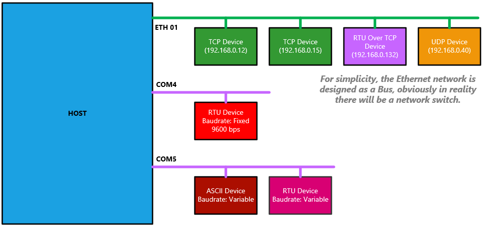
Suppose we choose the second option and therefore have two independent serial ports in our host, the first at 9600 bps to manage RTU Device slow and the second at 115200 bps to manage RTU Device fast and ASCII Device fast. The serial ports can be physical, which is very unusual today, or constituted by USB/RS485 adapters.
So, in conclusion, to manage our field, there will be 3 communication channels, one Ethernet and two RS485.
This will be our hardware configuration.
Addressess standardization
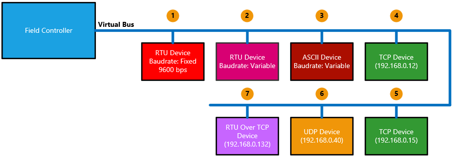
In order to work, the Field Controller, needs that the Devices Addresses (ID) must be unique, this because it holds a virtual bus. So, we need to assign an ID also to the network Devices (into our program of course, not physically).
| Device | ID | Physical port | Parameters | Proto/Format |
|---|---|---|---|---|
| RTU Device slow | 1 | COM4 | 9600, E, 8, 1 | RTU |
| RTU Device fast | 2 | COM5 | 115200, E, 8, 1 | RTU |
| ASCII Device | 3 | COM5 | 115200, E, 8, 1 | ASCII |
| TCP Device 1 | 4 | ETH 01 | 192.168.0.12:502 | TCP |
| TCP Device 2 | 5 | ETH 01 | 192.168.0.15:502 | TCP |
| UDP Device | 6 | ETH 01 | 192.168.0.40:502 | UDP |
| RTU Over TCP Device | 7 | ETH 01 | 192.168.0.132:502 | RTU Over TCP |
Tip
It’s more convenient assign low addresses to serial devices, since they must be set explicitly via hardware (or software configuration) and because some old Devices have a limited addressing range. For network devices, the ID is only a logical Index.
According to the previous table, this will be our field configuration.
Implementation and use
Now we are ready to implement our Field Controller in a very simply way, note, the “Broker”, inside the library, is the ancestor class of the Field Controller and the Client.
Tip
If we have many devices, a good practice could be to assign a mnemonic name to the Device ID using an integer constant, in order to avoid confusion when we write the data exchange code.
C# example
static SnapMBBroker Controller;

// Creates the FieldController
Controller = new SnapMBBroker();
// Setup
Controller.AddDevice(MBConsts.FormatRTU, 1, "COM4", 9600, 'N', 8, 1, MBConsts.FlowNONE);
Controller.AddDevice(MBConsts.FormatRTU, 2, "COM5", 115200, 'E', 8, 1, MBConsts.FlowNONE);
Controller.AddDevice(MBConsts.FormatASC, 3, "COM5", 115200, 'E', 8, 1, MBConsts.FlowNONE);
Controller.AddDevice(MBConsts.ProtoTCP, 4, "192.168.0.12", 502);
Controller.AddDevice(MBConsts.ProtoTCP, 5, "192.168.0.15", 502);
Controller.AddDevice(MBConsts.ProtoUDP, 6, "192.168.0.40", 502);
Controller.AddDevice(MBConsts.ProtoRTUOverTCP, 7, "192.168.0.132", 502);
// Read Data
Controller.ReadHoldingRegisters(1, 12, Amount, Device_1_Regs); // Read From RTU Device (1)
Controller.ReadHoldingRegisters(5, 1, Amount, Device_5_Regs);  // Read From TCP Device (5)
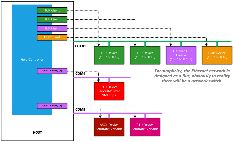
Technical insight
The Field Controller is a pass-through class container, it allocates a Network Client for each Network Device and allocates a Serial Controller (an internal class) for each “group” of serial devices which have the same Comport Name (however, a verification on the remaining parameters such as Baud rate, Data Bits etc. is made) Since it inherits from the “Broker”, it has all methods mapped onto the Modbus function, so, when a request is made (which contains the Device ID), it will use the ID to index the internal array containing the right Client (or Controller) and it will pass the request to it.
Using the Clients
Unlike the controller, a clients establish a peer-to-peer connection with the devices. Each Client communicates with only one Device but does so completely independently from the others. This allows us to create a multithreaded architecture
Info
All SnapModbus Objects are thread-safe
This type of architecture is very useful when the Devices need different scanning times, for example a Device that acquires the average air consumption can be interrogated every 2000ms, while the temperature of a thermoregulator could be collected every 500ms and, perhaps, the digital I/O of a palletizer need to be refreshed as soon as possible. As shown in the figure, we will create a thread that will manage its Client at regular intervals, independently from the others.

Using a sequential approach, we would have to have a refresh clock as high as the fastest Device and create some internal dividers to refresh the slower Devices, and this is quite annoying from a programming point of view. It is also not very efficient because, for example, Ethernet Devices, which can work simultaneously, would be refreshed one by one. Now, while we are used to using TCP Clients in multithreaded environments (each Client has its own socket), it is strange to think of independent serial clients when the communication channel is unique and cannot be shared.
The client management mechanism is shown in the next figure.

Each TCP (or UDP) client has its own socket that accesses the network independently from the others. Instead, when we create a serial client, it requests to the ChannelsManager (an internal class) a serial socket with the required characteristics (com port, speed, etc.). The ChannelsManager, if such socket does not exist, creates it, and returns its instance to the client, otherwise it returns the instance of an already created socket.
Each Client, when it must carry out a transaction (send request - wait for response), locks the serial socket, which will put any other clients "on hold" who want to access the Bus. At the end of the transaction the bus will be assigned to another client that was waiting.
This methodology allows us to unify the management of clients by greatly simplifying our code.
Conversely, during destruction, the serial manager manages a reference count for each serial socket.
Finally, if we realize that the serial bus is congested because we have many devices, we can install a second serial adapter and change only and exclusively the identifier of the com port in our clients.
Obviously, multithreading is a "feature", this means that it is possible to use the clients even refreshing them sequentially in the same thread without problems.
Tip
If we install multiple serial adapters, it is good practice to balance the workload, i.e., assign clients to adapters so that the percentage of bus usage times is equally distributed.
Concurrency
As mentioned, all SnapMB objects are thread-safe, this means you can use the same client in two different threads.
This is not a good practice, however, if you need to write "on demand" to another thread and don't want to allocate a new client, you can use this technique.
Generally the best strategy is to have one client per thread, but sometimes this is not possible because some TCP Devices, unlike SnapMB devices, cannot handle multiple connections.
Broadcast
Broadcast is the ability to send a function to all devices simultaneously. There are some key points:
This only makes sense for Modbus RTU where a Controller addresses its Devices at the protocol level (using the Device ID), in Modbus/TCP and its derivatives (UDP, RTU Over TCP and RTU Over UDP) the communication is peer- to-peer, so the devices are addressed using the underlying network protocol (IP address).
It can be used only for write functions.
Since the protocol is half-duplex, Devices receiving a Broadcast function will not respond.
Warning
The broadcast is unsafe because:
- Since there is no response from the Devices, we don't know if something was wrong.
- Devices can be very different from each other, so we are not sure about their resource limits (max registers/coil indexes).
The FieldController broadcasts all write functions with DeviceID = 0 to all serial devices, regardless of their physical adapter.
Device
Architecture
Similarly to the objects already seen, Client and Controller, even the Devices are polymorphic, i.e. there is only one Device which can be Ethernet or Serial and work with all the supported transport protocols.
However, due to different technologies, their behavior is different.
The TCP Device (which handles TCP and RTU Over TCP transports) is fully multithreaded and can serve multiple clients simultaneously. It is a full-fledged TCP server that creates a socket associated with a thread for each connection, which independently manages the requests.
The UDP Device (which manages UDP transports and RTU Over UDP) has a single thread but can service and arbitrate the requests of multiple UDP clients.
Both TCP and UDP Devices have a PeerList, which can be AllowList or BlockList, in which it is possible to store the IP addresses that can access or those whose consent is denied.
Finally, the Serial Device (which handles RTU and ASCII formats) has a single thread and handles requests from a single Client or Controller, since there is no concept of master address on the serial line.
User program Interface
The Device is a “request handler” i.e., an object that replies to the Client/Controller request. All this cannot happen in a completely autonomous way, it is necessary that our application is aware of this data exchange and that it can modify its behavior accordingly.
The Device, once created, communicates with our application through shared resources and/or callbacks.
Shared resources
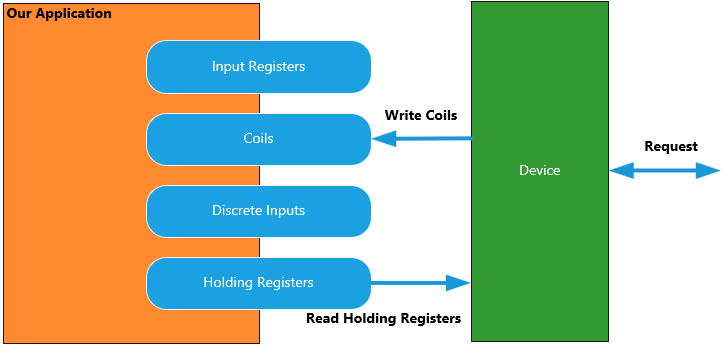
This is the most intuitive method, we allocate four memory areas in our application (struct or Array) and tell the Device: these are your Holding registers, Coils, Input registers and Discrete inputs; when the Controller requests to read or write something, you must use these areas.
Tip
It is not necessary to allocate all resources, we may only want to work with Coils and Holding Registers, for example.
Concurrency
The memory areas exist in our application, so we can access them at any time, however, since we do not know when the Device reads or writes to them, it is necessary to synchronize access to avoid reading "partial data".
To do this, the Device provides (see Lock/Unlock and Safe Copy Area methods that allow you to lock the memory area before accessing it.
Note
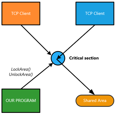
The lock/unlock mechanism for shared areas is at the application level, i.e. if you create two devices associated with two different addresses/ports, which work on the same shared areas, data consistency is valid for both the devices simultaneously.
If the logic of our program is like that of a PLC, that is cyclical sequential, it could be useful to work with a double buffer, i.e., mirror memory areas in which we can transfer the data to work on.
Concurrent access of multiple socket threads is also governed by a critical section, and this happens automatically.
Finally, if we need to know when a device has written/read data in a certain area, we can use the Event Callback (see below).
After the creation, to share a resource, you need of only one line of code:
Device.RegisterArea(<Area type>, <Area reference>, <Area Size>);
Example
// C#
Device.RegisterArea(MBConsts.mbaHoldingRegisters, ref HoldingRegisters, regs_amount);
// C++
Device->RegisterArea(mbaHoldingRegisters, &HoldingRegisters, regs_amount);
/* C */
device_RegisterArea(Device, mbaHoldingRegisters, &HoldingRegisters, regs_amount);
// Object Pascal
Device.RegisterArea(mbaHoldingRegisters, @HoldingRegisters, regs_amount);
Note
In C# to prevent the garbage collector action, which is not aware that a memory area is accessed from unmanaged code, the area is automatically “pinned” via a GCHandle. Have a look at RegisterArea() into SnapMB.net.cs
Callbacks
Callbacks are functions (implemented as Delegates in C#) in our code which are called by the Device when something happens. And usually, they are associated to a Modbus functions.
In other words, we can say to the Device: when you receive a request “0x08: Diagnostics” you must call this function.

Within the callback we have access to the information the client wants to write, or we can respond with the information it has asked to read.
There are 3 callback not associated to Modbus functions:
- Events (see below)
- PacketLog, which makes received and sent telegrams available in binary form.
- Passthrough, which can be used to write a gateway or a protocol converter.
Warning
the callback is executed in the device thread and its execution time determines the response time of the device towards the client, so:
- Pay attention to the resources you access; they should be thread-safe.
- Perform quick operations. For example, loading information to be sent from disk could cause the client to time out.
Also using the callbacks involve only one line of code:
Device.RegisterCallback(<Callback type>, <Function address>, usrPtr);
usrPtr is a value that the Device returns to us into the callback, it can be used to store an Object reference and can be set to NULL (nil or IntPtr.Zero) if we don’t need of it.
Shared resources vs Callbacks
Here some concepts:
- To handle Registers/Bit we can use Shared resources or Callbacks
- To handle all other functions, we can only use Callbacks
- If a callback was not set, the Device automatically issues the answer 0x01 exception error (that means the resource is not available / the function is not implemented)
- Register/Bit Management: if we have both Shared Resource and Callback, if the request is to write, the Shared Resources are used first, then the Callback is activated, the opposite if the operation is to read.
Log and Events
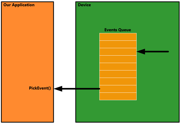
When something happens the Device create an Event (a struct containing some information), every event is inserted into an internal a circular queue and, if we set the DeviceEvent callback, it is called passing the event as parameter.
So, we can get events in two way, the first, synchronous, setting a Callback and consuming the event as soon as it is created.
The second, asynchronous, extracting in a polling cycle the event from the queue in another thread.
The first method is suggested when we want an immediate reaction to the event, knowing, for example, if a certain memory area was written.
The second for event logging, using PickEvent(Event) or directly PickEventAsText(string) which returns the textual representation of the event.
Into the examples supplied you will find both methods.
// Pascal WinForm example of a timer tick event which
// appends the device events into a Memo object
procedure TMainForm.timLogTimer(Sender: TObject);
var
    Message : string;
begin
    // Returns true if an event was picked, false if the queue is empty
    while Device.PickEventAsText(Message) do
        Log.Lines.Add(Message);
end;
Error handling
The Device autonomously manages the Modbus protocol, including its exceptions, this means that:
- If we have not shared a memory area for the Input Registers and we have not even allocated a callback to manage them, if a request to read these registers arrives, the Device, according to the specification, will respond with the exception error 0x01: Illegal function
- If we have allocated 256 registers and an access beyond this limit is requested, the device will respond with the exception error 0x02: Illegal data address
Gateway (Protocol Converter)
The Gateway is not a native SnapMB object, but it's very simple to implement using two special characteristics of the Device and the Controller:
- The Passthrough Event (Device)
- The RawRequest (Controller)
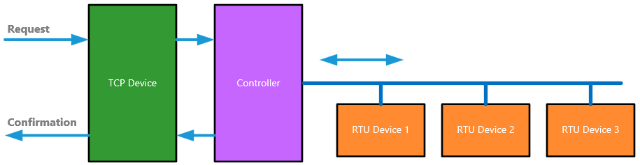
The gateway is a protocol converter, it contains a Device set to the source protocol and a Controller set to the target protocol.
When a request arrives, the Device relays it to the Controller which executes the request, then, the answer received by the Controller is relayed back to the Device.
The figure shows the principle diagram of a TCP/RTU Gateway, but, since our Controller manages a virtual bus, it is also possible to implement an RTU/TCP Gateway or others.
Into the examples you will also find the Gateway, however this is where the magic happens:
int SNAP_API PasstroughHandler(void* usrPtr, byte DeviceID, void* RxPDU, word RxPDUSize, void* TxPDU, word& TxPDUSize)
{
    // Relay the request through the client
    int rawResult = InnerClient->RawRequest(DeviceID, RxPDU, RxPDUSize, TxPDU, TxPDUSize, 0);

    // Converts Timeout and Hardware errors to be fully Modbus compliant
    if (rawResult != mbNoError)
    {
        // Timeout
        if ((rawResult & 0x0FFFFFFF) == 0x00050007)
            return errGatewayTargetFailed; // Target failed to respond
        // Other error (not Modbus protocol error)
        if (TxPDUSize == 0)
            return  errSlaveDeviceFailure; // Generic failure
    }
    return 0;
}
Serial Sniffer
It is possible to make a serial sniffer very simply in two different ways.
- Using a passthrough event like we did for the gateway
- Using the PacketLog event.
Both methods allow you to have access to all the telegrams that are intercepted by the Device on an RS485 line.
Api reference
SnapModbus functions are exported following “C” calling convention, and, since they internally are object oriented, there is always the object reference as parameter.
The Object reference is a struct defined as below:
typedef struct {
	uintptr_t Object;
	uintptr_t Selector;
}XOBJECT;
it consists of two "native integer", i.e. two integer that can be 32 or 64 bit wide, depending of way the build. Never change it, it must be just passed as parameter to the working functions.
Into the high-level wrappers, there are classes that incapsulate these functions, so, for example, you will not directly use the function:
Broker_ReadHoldingRegisters(XOBJECT &Broker, <Fun 0x03 parameters>)
Instead, you will call:
Client.ReadHoldingRegisters(<Fun 0x03 Parameters>); // C#, Object Pascal
Client->ReadHoldingRegisters(<Fun 0x03 Parameters>); // C++
More
Binary libraries cannot export overloaded functions, so, to create an Ethernet Client, in plain-c you must call the function:
void broker_CreateEthernetClient(XOBJECT& Broker, const char* Address, int Port, int Proto);
High-level object-oriented wrappers only have one class with overloaded constructors, so the type of the object will be determined by the parameter list.
Note
Here, except in special cases, the functions will be listed as exported by the library.
For high level syntax, please, refer to the wrappers
Client/Controller
Creation/Destruction
CreateFieldController()
void broker_CreateFieldController(XOBJECT& Broker);
Creates a Field Controller.
| Parameter | Values |
|---|---|
| Broker | Object descriptor returned |
CreateEthernetClient()
void broker_CreateEthernetClient(XOBJECT& Broker, int Proto, const char* Address, int Port);
Creates an Ethernet Client working with a given transport protocol
| Parameter | Values |
|---|---|
| Broker | Object descriptor returned |
| Proto | Transport Protocol |
| Address | Device IP Address e.g. "192.168.1.15" |
| Port | Device Port, usually 502 |
Transport protocol
| Value | Protocol |
|---|---|
| 0 | TCP |
| 1 | UDP |
| 2 | RTU Over TCP |
| 3 | RTU Over UDP |
CreateSerialClient()
void broker_CreateSerialClient(XOBJECT& Broker, int Format, const char* PortName, int BaudRate, char Parity, int DataBits, int Stops, int Flow);
Creates a Serial Client working with a given Data Format
| Parameter | Values |
|---|---|
| Broker | Object descriptor returned |
| Format | Data Format |
| PortName | Serial Channel Name as known to the host OS (1) |
| Baudrate | Speed (bps) e.g. 9600, 19200, 115200 ... |
| Parity | Frame parity |
| DataBits | Frame data bits : 7 or 8 |
| StopBits | Frame stop bits : 1 or 2 |
| Flow | Control Flow |
(1) In Windows it will be "COM1", "COM2" and so on.. In Linux/BSD/macOS, please refer to the device list into /dev
Format
| Value | Format |
|---|---|
| 0 | RTU |
| 1 | ASCII |
Parity
| Value | Parity |
|---|---|
| E or e | Even Parity |
| O or o | Odd Parity |
| N or n | No Parity |
Flow
| Value | Flow |
|---|---|
| 0 | No control flow |
| 1 | Hardware control flow (RTS/CTS) |
Destroy()
void broker_Destroy(XOBJECT& Broker);
Destroys the Object
| Parameter | Values |
|---|---|
| Broker | Object descriptor which came from the creation function |
Behaviour change
Sometime we don't know in advance the type of Client that we need, or we need to change its behavior at runtime.
While it's very easy to destroy and then recreate a client, sometimes using managed languages like C# it's better to let the garbage collector destroy our object. So there are three ChangeTo() methods which internally destroy the Client and then recreate it.
These helper methods are present only into the high-level wrappers, since low-level programming (like plain-c) doesn't need of them.
They are overloaded methods and have the same syntax of the constructors.
let's see the methods of C# since its syntax is halfway between C++ and Pascal.
ChangeTo()
// Changes the current Object to a Field Controller
public void ChangeTo()
// Changes the current Object to an Ethernet Client
public void ChangeTo(int Proto, string Address, int Port)
// Changes the current Object to a Serial Client
public void ChangeTo(int Format, string PortName, int BaudRate, char Parity, int DataBits, int Stops, int Flow)
Warning
Since the internal Object is destroyed, all it resources will be freed, so, if the current Object is a Field Controller, the devices list will be emptied, also if the new Object is a Field Controller itself.
Object control functions
Connect()
int broker_Connect(XOBJECT& Broker);
Connects the Broker.
| Object Type | Behavior |
|---|---|
| FieldController | Calls the Connection method for all inner objects (see below). Returns errSomeConnectionsError if some of them failed. |
| TCP Client | Connects to the Device. Returns an error if the connection failed due to refusion or invalid address |
| UDP Client | Simply creates the UDP Socket. |
| Serial Client | Opens the Serial Port. If the Serial Socket is shared among other Clients and it's already opened, nothing will happen. |
Note:
- RTU Over TCP is a Transport protocol of TCP Client
- RTU Over UDP is a Transport protocol of UDP Client
| Parameter | Values |
|---|---|
| Broker | Object descriptor which came from the creation function |
| Return | Meaning |
|---|---|
| 0 | Success |
| Other | See the error tables |
Disconnect()
int broker_Disconnect(XOBJECT& Broker);
Disconnects the Broker.
| Object Type | Behavior |
|---|---|
| FieldController | Calls the Disconnection method for all inner objects (see below) |
| TCP Client | Performs a TCP/IP disconnection to the Device and destroys the TCP socket. |
| UDP Client | Simply destroys the UDP Socket. |
| Serial Client | Closes the Serial Port. If the Serial Socket is shared among other Clients and it's already closed, nothing will happen. |
Note:
- RTU Over TCP is a Transport protocol of TCP Client
- RTU Over UDP is a Transport protocol of UDP Client
| Parameter | Values |
|---|---|
| Broker | Object descriptor which came from the creation function |
This function returns always 0 (success)
AddControllerXXXDevice()
int broker_AddControllerNetDevice(XOBJECT& Broker, int Proto, byte DeviceID, const char* Address, int Port);
int broker_AddControllerSerDevice(XOBJECT& Broker, int Format, byte DeviceID, const char* PortName, int BaudRate, char Parity, int DataBits, int Stops, int Flow);
Allocates a new target device into a FieldController as explained here
Since this involves a Client creation, the parameters are the same of its constructor.
The high-level wrappers expose this function as a single overloaded method named
AddDevice()
The list of parameters will determinate what function has to be called.
Example
// This will call broker_AddControllerNetDevice()
Controller.AddDevice(MBConsts.ProtoTCP, 1, "192.168.1.10", 502);
// This will call broker_AddControllerSerDevice()
Controller.AddDevice(MBConsts.FormatRTU, 1, "COM5", 19200, 'E', 8, 1, MBConsts.FlowNONE);
| Return | Meaning |
|---|---|
| 0 | Success |
| Other | See the error tables |
SetXXXParam()
int broker_SetLocalParam(XOBJECT& Broker, byte LocalID, int ParamIndex, int Value);
int broker_SetRemoteDeviceParam(XOBJECT& Broker, byte DeviceID, int ParamIndex, int Value);
The Local param refers to a Broker's parameter which is global, i.e., it modifies the Broker behavior against all Devices managed. The Remote Device param is specific of that Device managed.
E.g.
The Send Timeout is a local param because it belongs to the Broker and is the same for the transactions with all Devices.
The Auto Timeout flag is a remote param, every Device has its own.
These are Multiplex functions, e.g.
SetRemoteDeviceParam(1, par_FixedTimeout, 1500);
Will set the Receive timeout of the Device 1 to 1500 ms.
Where par_FixedTimeout is an integer constant = 9;
SetLocalParam(3, par_SendTimeout, 100);
If the Broker is a FieldController, will set to 100 ms the Send Timeout of the inner client who manages the Device N.3
Local Param
| Parameter | Values |
|---|---|
| Broker | Object descriptor which came from the creation function |
| LocalID | Inner client Index |
| ParamIndex | Parameter Index |
| Value | Value to set |
Note
If the Broker is a Client (not a FieldController) the LocalID param is ignored
Remote Param
| Parameter | Values |
|---|---|
| Broker | Object descriptor which came from the creation function |
| DeviceID | Remote device Address (ID) |
| ParamIndex | Parameter Index |
| Value | Value to set |
Refer here for the parameter list.
GetIoBufferXXX()
int broker_GetIOBufferPtr(XOBJECT& Broker, byte DeviceID, int BufferKind, pbyte &Data);
int broker_GetIOBuffer(XOBJECT& Broker, byte DeviceID, int BufferKind, pbyte Data);
After a transaction, it's possible to get the TX/RX buffer from the Broker. This is very useful for debug purpose.
broker_GetIOBufferPtr() Returns the pointer to the buffer choosed.
broker_GetIOBuffer() Directly copies the data into a given buffer.
The first is more fast because we can pass the pointer directly to a dump/storage function.
The second can be used in a managed environment (C#) where the use of pointers is tricky.
| Parameter | Values |
|---|---|
| Broker | Object descriptor which came from the creation function |
| DeviceID | Device ID if the Broker is a FieldController, otherwise is ignored. |
| BufferKind | The buffer choosed |
| &Data | Pointer to the buffer containing the data |
| Data | Area pointer where the data must to be copied |
BufferKind
| Value | BufferKind |
|---|---|
| 0 (bkSnd) | Data sent |
| 1 (bkRcv) | Data received |
| Return | Meaning |
|---|---|
| int Value | Buffer size (byte) |
GetDeviceStatus()
int broker_GetDeviceStatus(XOBJECT& Broker, byte DeviceID, TDeviceStatus& DeviceStatus);
Reads the status of a given device.
| Parameter | Values |
|---|---|
| Broker | Object descriptor which came from the creation function |
| DeviceID | Remote device Address (ID), ignored if the Broker is a Client |
| DeviceStatus | Reference (Pointer to) of a TDeviceStatus struct |
TDeviceStatus struct
typedef struct {
    int32_t LastError;
    int32_t Status;
    int32_t Connected;
    uint32_t JobTime;
}TDeviceStatus;
| Field | Meaning |
|---|---|
| LastError | Last transaction error code (0 = success) |
| Status | Internal status after the last transaction |
| Connected | 0 : Not connected; 1 : Connected |
| JobTime | Last transaction time (ms) |
Internal status
| Value | Meaning |
|---|---|
| 0 : Unknown | Status unknown (maybe already created) |
| 1 : OK | OK |
| 2 : Timeout | Last transaction was timed out |
| 3 : HWError | Socket or Serial port read/write error |
| 4 : ProtoError | The device returned a Modbus error |
Modbus Functions
Note
Please refer to MODBUS APPLICATION PROTOCOL SPECIFICATION V1.1b3 for the "Modbus" behavior of following functions
ReadCoils()
int broker_ReadCoils(XOBJECT& Broker, byte DeviceID, word Address, word Amount, void* pUsrData);
Implementation of function (0x01)
| Parameter | Values |
|---|---|
| Broker | Object descriptor which came from the creation function |
| DeviceID | Device ID if the Broker is a FieldController, otherwise is ignored. |
| Address | Start address (first item index) |
| Amount | Items number to transfer |
| pUsrData | Pointer to transfer buffer |
Note
With this function it is possible to overcome the limits of the Modbus specifications by transferring up to 65535 items.
If the number of items is greater than the PDU size, the function automatically splits the request into several consecutive transactions.
| Return | Meaning |
|---|---|
| 0 | Success |
| Other | See the error tables |
ReadDiscreteInputs()
int broker_ReadDiscreteInputs(XOBJECT& Broker, byte DeviceID, word Address, word Amount, void* pUsrData);
Implementation of function (0x02)
| Parameter | Values |
|---|---|
| Broker | Object descriptor which came from the creation function |
| DeviceID | Device ID if the Broker is a FieldController, otherwise is ignored. |
| Address | Start address (first item index) |
| Amount | Items number to transfer |
| pUsrData | Pointer to transfer buffer |
Note
With this function it is possible to overcome the limits of the Modbus specifications by transferring up to 65535 items.
If the number of items is greater than the PDU size, the function automatically splits the request into several consecutive transactions.
| Return | Meaning |
|---|---|
| 0 | Success |
| Other | See the error tables |
ReadHoldingRegisters()
int broker_ReadHoldingRegisters(XOBJECT& Broker, byte DeviceID, word Address, word Amount, void* pUsrData);
Implementation of function (0x03)
| Parameter | Values |
|---|---|
| Broker | Object descriptor which came from the creation function |
| DeviceID | Device ID if the Broker is a FieldController, otherwise is ignored. |
| Address | Start address (first item index) |
| Amount | Items number to transfer |
| pUsrData | Pointer to transfer buffer |
Note
With this function it is possible to overcome the limits of the Modbus specifications by transferring up to 65535 items.
If the number of items is greater than the PDU size, the function automatically splits the request into several consecutive transactions.
| Return | Meaning |
|---|---|
| 0 | Success |
| Other | See the error tables |
ReadInputRegisters()
int broker_ReadInputRegisters(XOBJECT& Broker, byte DeviceID, word Address, word Amount, void* pUsrData);
Implementation of function (0x04)
| Parameter | Values |
|---|---|
| Broker | Object descriptor which came from the creation function |
| DeviceID | Device ID if the Broker is a FieldController, otherwise is ignored. |
| Address | Start address (first item index) |
| Amount | Items number to transfer |
| pUsrData | Pointer to transfer buffer |
Note
With this function it is possible to overcome the limits of the Modbus specifications by transferring up to 65535 items.
If the number of items is greater than the PDU size, the function automatically splits the request into several consecutive transactions.
| Return | Meaning |
|---|---|
| 0 | Success |
| Other | See the error tables |
WriteSingleCoil()
Implementation of function (0x05)
int broker_WriteSingleCoil(XOBJECT& Broker, byte DeviceID, word Address, word Value);
| Parameter | Values |
|---|---|
| Broker | Object descriptor which came from the creation function |
| DeviceID | Device ID if the Broker is a FieldController, otherwise is ignored. |
| Address | Start address (first item index) |
| Value | Value to write |
| Return | Meaning |
|---|---|
| 0 | Success |
| Other | See the error tables |
WriteMultipleRegisters()
int broker_WriteMultipleRegisters(XOBJECT& Broker, byte DeviceID, word Address, word Amount, void* pUsrData);
Implementation of function (0x10)
| Parameter | Values |
|---|---|
| Broker | Object descriptor which came from the creation function |
| DeviceID | Device ID if the Broker is a FieldController, otherwise is ignored. |
| Address | Start address (first item index) |
| Amount | Items number to transfer |
| pUsrData | Pointer to transfer buffer |
Note
With this function it is possible to overcome the limits of the Modbus specifications by transferring up to 65535 items.
If the number of items is greater than the PDU size, the function automatically splits the request into several consecutive transactions.
| Return | Meaning |
|---|---|
| 0 | Success |
| Other | See the error tables |
WriteSingleRegister()
int broker_WriteSingleRegister(XOBJECT& Broker, byte DeviceID, word Address, word Value);
Implementation of function (0x06)
| Parameter | Values |
|---|---|
| Broker | Object descriptor which came from the creation function |
| DeviceID | Device ID if the Broker is a FieldController, otherwise is ignored. |
| Address | Start address (first item index) |
| Value | Value to write |
| Return | Meaning |
|---|---|
| 0 | Success |
| Other | See the error tables |
ReadWriteMultipleRegisters()
int broker_ReadWriteMultipleRegisters(XOBJECT& Broker, byte DeviceID, word RDAddress, word RDAmount, word WRAddress, word WRAmount, void* pRDUsrData, void* pWRUsrData);
Implementation of function (0x17)
| Parameter | Values |
|---|---|
| Broker | Object descriptor which came from the creation function |
| DeviceID | Device ID if the Broker is a FieldController, otherwise is ignored. |
| RDAddress | Start address (first item index) to be read |
| RDAmount | Items number to read |
| WRAddress | Start address (first item index) to be write |
| WRAmount | Items number to write |
| pRDUsrData | Pointer to read buffer |
| pWRUsrData | Pointer to write buffer |
| Return | Meaning |
|---|---|
| 0 | Success |
| Other | See the error tables |
WriteMultipleCoils()
int broker_WriteMultipleCoils(XOBJECT& Broker, byte DeviceID, word Address, word Amount, void* pUsrData);
Implementation of function (0x0F)
| Parameter | Values |
|---|---|
| Broker | Object descriptor which came from the creation function |
| DeviceID | Device ID if the Broker is a FieldController, otherwise is ignored. |
| Address | Start address (first item index) |
| Amount | Items number to transfer |
| pUsrData | Pointer to transfer buffer |
Note
With this function it is possible to overcome the limits of the Modbus specifications by transferring up to 65535 items.
If the number of items is greater than the PDU size, the function automatically splits the request into several consecutive transactions.
| Return | Meaning |
|---|---|
| 0 | Success |
| Other | See the error tables |
MaskWriteRegister()
int broker_MaskWriteRegister(XOBJECT& Broker, byte DeviceID, word Address, word AND_Mask, word OR_Mask);
Implementation of function (0x16)
| Parameter | Values |
|---|---|
| Broker | Object descriptor which came from the creation function |
| DeviceID | Device ID if the Broker is a FieldController, otherwise is ignored. |
| Address | Register Index |
| AND_Mask | AND Mask |
| OR_Mask | OR Mask |
This function code is used to modify the contents of a specified holding register using a combination of an AND mask, an OR mask, and the register's current contents. The function can be used to set or clear individual bits in the register.
The function’s algorithm is:
Result = (Current_Content AND AND_Mask) OR (OR_Mask AND (NOT AND_Mask))
| Return | Meaning |
|---|---|
| 0 | Success |
| Other | See the error tables |
ReadFileRecord()
int broker_ReadFileRecord(XOBJECT& Broker, byte DeviceID, byte RefType, word FileNumber, word RecNumber, word RegsAmount, void* RecData);
Implementation of function (0x14)
| Parameter | Values |
|---|---|
| Broker | Object descriptor which came from the creation function |
| DeviceID | Device ID if the Broker is a FieldController, otherwise is ignored. |
| RefType | Reference type (must be 6) |
| FileNumber | File Number to access |
| RecNumber | Record Number to read |
| RegsAmount | Number of registers to transfer |
| RecData | Pointer to Record data |
Note
To simplify the use into the user program, I decided to avoid the use of nested structures, so this functions limits the number of record to be read to 1
| Return | Meaning |
|---|---|
| 0 | Success |
| Other | See the error tables |
WriteFileRecord()
int broker_WriteFileRecord(XOBJECT& Broker, byte DeviceID, byte RefType, word FileNumber, word RecNumber, word RegsAmount, void* RecData);
Implementation of function (0x15)
| Parameter | Values |
|---|---|
| Broker | Object descriptor which came from the creation function |
| DeviceID | Device ID if the Broker is a FieldController, otherwise is ignored. |
| RefType | Reference type (must be 6) |
| FileNumber | File Number to access |
| RecNumber | Record Number to write |
| RegsAmount | Number of registers to transfer |
| RecData | Pointer to Record data |
Note
To simplify the use into the user program, I decided to avoid the use of nested structures, so this functions limits the number of record to write to 1
| Return | Meaning |
|---|---|
| 0 | Success |
| Other | See the error tables |
ReadFIFOQueue()
int broker_ReadFIFOQueue(XOBJECT& Broker, byte DeviceID, word Address, word& FifoCount, void* FIFO);
Implementation of function (0x18)
| Parameter | Values |
|---|---|
| Broker | Object descriptor which came from the creation function |
| DeviceID | Device ID if the Broker is a FieldController, otherwise is ignored. |
| Address | Start register address (FIFO Index) |
| FifoCount | Number of registers which were read |
| FIFO | Pointer to our FIFO area (should contain at least 32 registers) |
| Return | Meaning |
|---|---|
| 0 | Success |
| Other | See the error tables |
ReadExceptionStatus()
int broker_ReadExceptionStatus(XOBJECT& Broker, byte DeviceID, byte& Data);
Implementation of function (0x07)
| Parameter | Values |
|---|---|
| Broker | Object descriptor which came from the creation function |
| DeviceID | Device ID if the Broker is a FieldController, otherwise is ignored. |
| Data | Will contain the Device status |
The normal response contains the status of the eight Exception Status outputs.
The outputs are packed into one data byte, with one bit per output.
The status of the lowest output
reference is contained in the least significant bit of the byte.
The contents of the eight Exception Status outputs are device specific.
| Return | Meaning |
|---|---|
| 0 | Success |
| Other | See the error tables |
Diagnostics()
int broker_Diagnostics(XOBJECT& Broker, byte DeviceID, word SubFunction, void* pSendData, void* pRecvData, word ItemsToSend, word& ItemsRecvd);
Implementation of function (0x08)
| Parameter | Values |
|---|---|
| Broker | Object descriptor which came from the creation function |
| DeviceID | Device ID if the Broker is a FieldController, otherwise is ignored. |
| SubFunction | Request Sub function |
| pSendData | Pointer to data to send (our output buffer) |
| ItemsToSend | Items to send (each item is 16 bit wide) |
| ItemsRecvd | Items received (number of 16 bit words) |
| Return | Meaning |
|---|---|
| 0 | Success |
| Other | See the error tables |
GetCommEventCounter()
int broker_GetCommEventCounter(XOBJECT& Broker, byte DeviceID, word& Status, word& EventCount);
Implementation of function (0x0B)
| Parameter | Values |
|---|---|
| Broker | Object descriptor which came from the creation function |
| DeviceID | Device ID if the Broker is a FieldController, otherwise is ignored. |
| Status | Status word (returned) |
| EventCount | Events count (returned) |
| Return | Meaning |
|---|---|
| 0 | Success |
| Other | See the error tables |
GetCommEventLog()
int broker_GetCommEventLog(XOBJECT& Broker, byte DeviceID, word& Status, word& EventCount, word& MessageCount, word& NumItems, void* Events);
Implementation of function (0x0C)
| Parameter | Values |
|---|---|
| Broker | Object descriptor which came from the creation function |
| DeviceID | Device ID if the Broker is a FieldController, otherwise is ignored. |
| Status | Status word (returned) |
| EventCount | Events count (returned) |
| MessageCount | Message Counter (returned) (*) |
| RegsAmount | Number of registers to transfer |
| NumItems | Number of items read (every event is one byte) |
| Events | Pointer to our incoming data buffer |
(*) The message counter contains the quantity of messages processed by the remote device since its last restart, clear counters operation, or power–up.
| Return | Meaning |
|---|---|
| 0 | Success |
| Other | See the error tables |
ReportServerID()
int broker_ReportServerID(XOBJECT& Broker, byte DeviceID, void* pUsrData, int& DataSize);
Implementation of function (0x11)
| Parameter | Values |
|---|---|
| Broker | Object descriptor which came from the creation function |
| DeviceID | Device ID if the Broker is a FieldController, otherwise is ignored. |
| pUsrData | Pointer to our incoming data buffer |
| DataSize | Number of byte read (returned) |
| Return | Meaning |
|---|---|
| 0 | Success |
| Other | See the error tables |
ExecuteMEIFunction()
int broker_ExecuteMEIFunction(XOBJECT& Broker, byte DeviceID, byte MEI_Type, void* pWRUsrData, word WRSize, void* pRDUsrData, word& RDSize);
Implementation of function (0x2B)
MEI stands for Modbus Encapsulated Interface, i.e., this is a tunnel function.
| Parameter | Values |
|---|---|
| Broker | Object descriptor which came from the creation function |
| DeviceID | Device ID if the Broker is a FieldController, otherwise is ignored. |
| MEI_Type | MEI Type |
| pWRUsrData | Pointer to our outcoming buffer |
| WRSize | Size (byte) to send |
| pRDUsrData | Pointer to our incoming buffer |
| RDSize | Size (byte) received |
| Return | Meaning |
|---|---|
| 0 | Success |
| Other | See the error tables |
CustomFunctionRequest()
int broker_CustomFunctionRequest(XOBJECT& Broker, byte DeviceID, byte UsrFunction, void* pUsrPDUWrite, word SizePDUWrite, void* pUsrPDURead, word& SizePDURead, word SizePDUExpected);
This function can execute an User Modbus Function, i.e., a function not covered bye Modbus specifications
Note
SnapModbus only checks that the function number is not an "error response" i.e., the bit 7 must be zero
| Parameter | Values |
|---|---|
| Broker* | Object descriptor which came from the creation function |
| DeviceID* | Device ID if the Broker is a FieldController, otherwise is ignored. |
| UsrFunction* | User function code |
| pUsrPDUWrite* | Pointer to our outcoming PDU buffer |
| SizePDUWrite* | Size (byte) to send |
| pUsrPDURead* | Pointer to our incoming PDU buffer |
| SizePDURead* | Size (byte) received |
| SizePDUExpected* | Size (byte) expected (*) |
(*) If you know in advance the expected data size, otherwise pass 0.
This could be useful for serial communication to optimize the incoming telegram build.
For Ethernet communication this is meaningless.
| Return | Meaning |
|---|---|
| 0 | Success |
| Other | See the error tables |
RawRequest()
int broker_RawRequest(XOBJECT& Broker, byte DeviceID, void* pUsrPDUWrite, word SizePDUWrite, void* pUsrPDURead, word& SizePDURead, word SizePDUExpected);
This is a low-level function that allow to send/receive an arbitrary PDU
Note
SnapModbus will manage the transaction calculating the in/out CRC, if needed, (RTU/ASCII) or creating the MBAP header (TCP/UDP)
| Parameter | Values |
|---|---|
| Broker | Object descriptor which came from the creation function |
| DeviceID | Device ID if the Broker is a FieldController, otherwise is ignored. |
| pUsrPDUWrite | Pointer to our outcoming PDU buffer |
| SizePDUWrite | Size (byte) to send |
| pUsrPDURead | Pointer to our incoming PDU buffer |
| SizePDURead | Size (byte) received |
| SizePDUExpected | Size (byte) expected (*) |
(*) If you know in advance the expected data size, otherwise pass 0.
This could be useful for serial communication to optimize the incoming telegram build.
For Ethernet communication this is meaningless.
| Return | Meaning |
|---|---|
| 0 | Success |
| Other | See the error tables |
Device
Creation/Destruction
CreateEthernetDevice()
void device_CreateEthernet(XOBJECT& Device, int Proto, byte DeviceID, const char* Address, int Port);
Creates an Ethernet Device working with a given transport protocol
| Parameter | Values |
|---|---|
| Device | Object descriptor returned |
| Proto | Transport Protocol |
| DeviceID | Device Address (ID) |
| Address | Device IP Address e.g. "192.168.1.15" |
| Port | Device Port, usually 502 |
| Value | Protocol |
|---|---|
| 0 | TCP |
| 1 | UDP |
| 2 | RTU Over TCP |
| 3 | RTU Over UDP |
CreateSerialDevice()
void device_CreateSerial(XOBJECT& Device, int Format, byte DeviceID, const char* PortName, int BaudRate, char Parity, int DataBits, int Stops, int Flow);
Creates a Serial Device working with a given Data Format
| Parameter | Values |
|---|---|
| Device | Object descriptor returned |
| Format | Data Format |
| DeviceID | Device Address (ID) |
| PortName | Serial Channel Name as known to the host OS (1) |
| Baudrate | Speed (bps) e.g. 9600, 19200, 115200 ... |
| Parity | Frame Parity |
| DataBits | Frame data bits : 7 or 8 |
| StopBits | Frame stop bits : 1 or 2 |
| Flow | Control Flow |
(1) In Windows it will be "COM1", "COM2" and so on.. In Linux/BSD/macOS, please refer to the device list into /dev
Format
| Value | Format |
|---|---|
| 0 | RTU |
| 1 | ASCII |
Parity
| Value | Parity |
|---|---|
| E or e | Even Parity |
| O or o | Odd Parity |
| N or n | No Parity |
Flow
| Value | Flow |
|---|---|
| 0 | No control flow |
| 1 | Hardware control flow (RTS/CTS) |
Destroy()
void device_Destroy(XOBJECT& Device);
Destroys the Object
| Parameter | Values |
|---|---|
| Device | Object descriptor which came from the creation function |
Object control functions
SetParam()
int device_SetParam(XOBJECT& Device, int ParamIndex, int Value);
These parameters apply directly to the Device, it's similar to Broker's SetLocalParam()
| Parameter | Values |
|---|---|
| Device | Object descriptor which came from the creation function |
| ParamIndex | Parameter Index |
| Value | Value to set |
Refer here for the parameter list.
| Return | Meaning |
|---|---|
| 0 | Success |
| Other | See the error tables |
GetSerialInterframe()
int device_GetSerialInterframe(XOBJECT& Device, int& InterframeDelay, int& MaxInterframeDetected);
This is a debug/tuning function that allow us to know the max spourious interframe (ms) detected into the last transaction. Have a look to Serial communications.
It's specific for serial communications. For TCP/UDP Devices this is not used.
| Parameter | Values |
|---|---|
| Device* | Object descriptor which came from the creation function |
| InterframeDelay* | The value that we set with par_InterframeDelay |
| MaxInterframeDetected* | Value to set |
| Return | Meaning |
|---|---|
| 0 | Success |
| Other | See the error tables |
SetCustomFunction()
int device_SetCustomFunction(XOBJECT& Device, byte FunctionID, int Value);
This function allows to enable/disable a given user-defined function into the Device.
| Parameter | Values |
|---|---|
| Device | Object descriptor which came from the creation function |
| FunctionID | Function number |
| Value | 1 : Enables the function, 0 : Disables it |
When an user function is enabled, the user function callback is called (if set).
only one callback is used for all user functions, see examples below.
| Return | Meaning |
|---|---|
| 0 | Success |
| Other | See the error tables |
C#
// Declare the delegate (common for all user functions)
static readonly TUsrFunctionRequest UsrFunctionRequest = new TUsrFunctionRequest(OnUserFunction);

// Into the body (main or other method) set 2 user functions and the callback
Device.SetCustomFunction(0x41, true);
Device.SetCustomFunction(0x42, true);
Device.RegisterCallback(MBConsts.cbkUsrFunction, Marshal.GetFunctionPointerForDelegate(UsrFunctionRequest), IntPtr.Zero);

// Callback code
static int OnUserFunction(IntPtr usrPtr, byte Function, IntPtr RxPDU, int RxPDUSize, IntPtr TxPDU, ref ushort TxPDUSize)
{
   if (Function == 0x41)
   {
       // Do something
   }
   if (Function == 0x42)
   {
       // Do something else
   }
   return 0;
}
Delphi/Lazarus
// Into the body (main or other method) set 2 user functions and the callback
Device.SetCustomFunction($41, true);
Device.SetCustomFunction($42, true);
Device.RegisterCallback(cbkUsrFunction, @OnUserFunction, nil);

// Callback code
function OnUserFunction(usrPtr : Pointer; UsrFunction : byte; RxPDU : Pointer;
  RxPDUSize : word; TxPDU : Pointer; var TxPDUSize : word) : integer;
{$IFDEF MSWINDOWS}stdcall;{$ELSE}cdecl;{$ENDIF}
begin
  if UsrFunction = $41 then
  begin
      // Do something
  end;
  if UsrFunction = $42 then
  begin
      // Do something else...
  end;
  Result := 0;
end;
C++
// Into the body (main or other method) set 2 user functions and the callback
Device->SetCustomFunction(0x41, true);
Device->SetCustomFunction(0x42, true);
Device->RegisterCallback(cbkUsrFunction, (void*)OnUserFunction, NULL);

// Callback code (SNAP_API = __stdcall in Windows, nothing in Linux/FreeBSD/macOS)
int SNAP_API OnUserFunction(void* usrPtr, byte Function, void* RxPDU, uint16_t RxPDUSize, void* TxPDU, uint16_t& TxPDUSize)
{
    if (Function == 0x41)
    {
        // Do something
    }
    if (Function == 0x42)
    {
        // Do something else
    }
    return 0;
}
Start()
int device_Start(XOBJECT& Device);
The device is started according to the set parameters.
TCP Device : The listener thread is created and the TCP socket is bound to the IP Address : Port
UDP Device : The listener thread is created and the UDP socket is bound to the IP Address : Port
SER Device : The listener thread is created and the Serial socket is bound to the port.
Note
In Unix-derived operating systems, to bind port 502 an application must have root privileges (must be run withsudo)
| Parameter | Values |
|---|---|
| Device | Object descriptor which came from the creation function |
| Return | Meaning |
|---|---|
| 0 | Success |
| Other | See the error tables |
Stop()
int device_Stop(XOBJECT& Device);
The device is stopped, all sockets are destroyed and all thread are closed.
| Parameter | Values |
|---|---|
| Device | Object descriptor which came from the creation function |
| Return | Meaning |
|---|---|
| Always 0 | Success |
BindEthernet()/BindSerial()
int device_BindEthernet(XOBJECT& Device, byte DeviceID, const char* Address, int Port);
int device_BindSerial(XOBJECT& Device, byte DeviceID, const char* PortName, int BaudRate, char Parity, int DataBits, int Stops, int Flow);
these functions allow you to (re)bind the Device to different Addresses/Ports.
The device must not be running.
BindEthernet()
| Parameter | Values |
|---|---|
| Device | Object descriptor returned |
| DeviceID | Device Address (ID) |
| Address | Device IP Address e.g. "192.168.1.15" |
| Port | Device Port, usually 502 |
BindSerial()
| Parameter | Values |
|---|---|
| Device | Object descriptor returned |
| DeviceID | Device Address (ID) |
| PortName | Serial Channel Name as known to the host OS (1) |
| Baudrate | Speed (bps) e.g. 9600, 19200, 115200 ... |
| Parity | Frame Parity |
| DataBits | Frame data bits : 7 or 8 |
| StopBits | Frame stop bits : 1 or 2 |
| Flow | Control Flow |
(1) In Windows it will be "COM1", "COM2" and so on.. In Linux/BSD/macOS, please refer to the device list into /dev
Parity
| Value | Parity |
|---|---|
| E or e | Even Parity |
| O or o | Odd Parity |
| N or n | No Parity |
Flow
| Value | Flow |
|---|---|
| 0 | No control flow |
| 1 | Hardware control flow (RTS/CTS) |
| Return (both functions) | Meaning |
|---|---|
| 0 | Success |
| Other | See the error tables |
AddPeer()
int device_AddPeer(XOBJECT& Device, const char* Address);
A new item is inserted into the Peer List (Only TCP/UDP Devices)
Have a look at par_DevPeerListMode here
| Parameter | Values |
|---|---|
| Device | Object descriptor which came from the creation function |
| Address | IP Address to insert (e.g. "192.168.1.34") |
| Return | Meaning |
|---|---|
| 0 | Success |
| Other | See the error tables |
RegisterArea()
int device_RegisterArea(XOBJECT& Device, int AreaID, void* Data, int Amount);
A shared resource is registered.
| Parameter | Values |
|---|---|
| Device | Object descriptor which came from the creation function |
| AreaID | Area Identifier (see below) |
| Data | Pointer to Area (or Area reference) |
| Amount | Number of items to share (bits or registers) |
| Return | Meaning |
|---|---|
| 0 | Success |
| Other | See the error tables |
| AreaID (mnemonic) | Value | Resource |
|---|---|---|
| mbAreaDiscreteInputs | 0 | Discrete Inputs |
| mbAreaCoils | 1 | Coils |
| mbAreaInputRegisters | 2 | Input Registers |
| mbAreaHoldingRegisters | 3 | Holding Registers |
When an Area is registered an internal Critical Section Object is created; it will used by LockArea()/UnlockArea() functions.
Sharing regs_amount registers using an array of 16 bit words.
C#
// Area declaration
static ushort[] HoldingRegisters = new ushort[regs_amount];
// Area registering
Device.RegisterArea(MBConsts.mbaHoldingRegisters, ref HoldingRegisters, regs_amount);
C++
// Area declaration
uint16_t HoldingRegisters[regs_amount];
// Area registering
Device->RegisterArea(mbAreaHoldingRegisters, &HoldingRegisters, regs_amount);
Delphi/Lazarus
// Area declaration
HoldingRegisters : packed array[0..regs_amount-1] of word;
// Area registering
Device.RegisterArea(mbAreaHoldingRegisters, @HoldingRegisters, regs_amount);
LockArea()/UnlockArea()
int device_LockArea(XOBJECT& Device, int AreaID);
int device_UnlockArea(XOBJECT& Device, int AreaID);
With these function we can manage the concurrent access to the shared areas as explained here
| Parameter | Values |
|---|---|
| Device | Object descriptor which came from the creation function |
| AreaID | Area Identifier, same as RegisterArea() see above |
| Return | Meaning |
|---|---|
| 0 | Success |
| Other | See the error tables |
This assures us that it will never happen that a client can read from the three registers old and new data at the same time.
Delphi/Lazarus
LockArea(mbaHoldingRegisters);
try
    HoldingRegisters[1]:=NewValue_1;
    HoldingRegisters[2]:=NewValue_2;
    HoldingRegisters[3]:=NewValue_3;
finally // to ensure to ever unlock the area
    UnlockArea(mbaHoldingRegisters);
end;
CopyArea()
int device_CopyArea(XOBJECT& Device, int AreaID, word Address, word Amount, void* Data, int CopyMode);
Allows to safely copy a shared area.
See here why you need of it.
It executes in sequence:
- LockArea()
- Copy
- UnlockArea()
| Parameter | Values |
|---|---|
| Device | Object descriptor which came from the creation function |
| AreaID | Area Identifier (see below) |
| Address | Start Index of shared area |
| Amount | Number of items to copy (bits or registers) |
| Data | Pointer to user Buffer |
| CopyMode | Copy direction (see below) |
| CopyMode | Values |
|---|---|
| 0 (Read) | The area is copied into our Buffer |
| 1 (Write) | Our Buffer is copied into the Area |
| AreaID (mnemonic) | Value | Resource |
|---|---|---|
| mbAreaDiscreteInputs | 0 | Discrete Inputs |
| mbAreaCoils | 1 | Coils |
| mbAreaInputRegisters | 2 | Input Registers |
| mbAreaHoldingRegisters | 3 | Holding Registers |
| Return | Meaning |
|---|---|
| 0 | Success |
| Other | See the error tables |
Note
If Start + Amount is greater than the Area limit, Amount is "trimmed" (no error is iussed)
PickEvent()/PickEventAsText()
int device_PickEvent(XOBJECT& Device, void* pEvent);
int device_PickEventAsText(XOBJECT& Device, char* Text, int TextSize);
Extract an event from the internal queue as explained here
The first returns the Event (to be analyzed), the second one its textual representation (for log purpose).
| Parameter | Values |
|---|---|
| Device | Object descriptor which came from the creation function |
| pEvent | Pointer to the event |
| Text | Pointer to an Array of Ansi chars |
| TextSize | Array size |
| Return | Meaning |
|---|---|
| 0 | The queue is empty, nothing was extracted |
| 1 | Event or Text contains the extracted item |
GetDeviceInfo()
int device_GetDeviceStatus(XOBJECT& Device, TDeviceInfo& DeviceInfo);
Reads the Device status
| Parameter | Values |
|---|---|
| Device | Object descriptor which came from the creation function |
| DeviceInfo | Reference (Pointer to) of a TDeviceInfo struct |
TDeviceStatus struct
typedef struct {
    int32_t Running;
    int32_t ClientsCount;   // only for TCP
    int32_t ClientsBlocked; // only for TCP/UDP
    int32_t LastError;
}TDeviceInfo;
| Field | Meaning |
|---|---|
| Running | 0 : Not running; 1 : Running |
| ClientsCount | Only TCP: number of connected clients |
| ClientsBlocked | Only TCP/UDP : number of blocked clients (*) |
| LastError | Last Device error code (0 = success) |
| JobTime | 0 : Not used here |
(*) See par_DevPeerListMode here
RegisterCallback()
int device_RegisterCallback(XOBJECT& Device, int CallbackID, void* cbRequest, void* UsrPtr);
A callback is registered, as explained here
| Parameter | Values |
|---|---|
| Device | Object descriptor which came from the creation function |
| CallbackID | Callback Selector (see below) |
| cbRequest | Pointer to Callback (or Callback reference) |
| UsrPtr | An user pointer returned unmodified by the Callback |
| Return | Meaning |
|---|---|
| 0 | Success |
| Other | See the error tables |
| Callback selector | value |
|---|---|
| cbkDeviceEvent | 0 |
| cbkPacketLog | 1 |
| cbkDiscreteInputs | 2 |
| cbkCoils | 3 |
| cbkInputRegisters | 4 |
| cbkHoldingRegisters | 5 |
| cbkReadWriteRegisters | 6 |
| cbkMaskRegister | 7 |
| cbkFileRecord | 8 |
| cbkExceptionStatus | 9 |
| cbkDiagnostics | 10 |
| cbkGetCommEventCounter | 11 |
| cbkGetCommEventLog | 12 |
| cbkReportServerID | 13 |
| cbkReadFIFOQueue | 14 |
| cbkEncapsulatedIT | 15 |
| cbkUsrFunction | 16 |
| cbkPassthrough | 17 |
Callbacks prototypes
these are the prototypes as they are declared.
typedef void (SNAP_API* pfn_DeviceEvent)(void* usrPtr, void* PEvent, int Size);
typedef void (SNAP_API* pfn_PacketLog)(void* usrPtr, longword Peer, int Direction, void* Data, int Size);
typedef int (SNAP_API* pfn_DiscreteInputsRequest)(void* usrPtr, word Address, word Amount, void* Data);
typedef int (SNAP_API* pfn_CoilsRequest)(void* usrPtr, int Action, word Address, word Amount, void* Data);
typedef int (SNAP_API* pfn_InputRegistersRequest)(void* usrPtr, word Address, word Amount, void* Data);
typedef int (SNAP_API* pfn_HoldingRegistersRequest)(void* usrPtr, int Action, word Address, word Amount, void* Data);
typedef int (SNAP_API* pfn_ReadWriteMultipleRegistersRequest)(void* usrPtr, word RDAddress, word RDAmount, void* RDData, word WRAddress, word WRAmount, void* WRData);
typedef int (SNAP_API* pfn_MaskRegisterRequest)(void* usrPtr, word Address, word AND_Mask, word OR_Mask);
typedef int (SNAP_API* pfn_FileRecordRequest)(void* usrPtr, int Action, word RefType, word FileNumber, word RecNumber, word RegsAmount, void* Data);
typedef int (SNAP_API* pfn_ExceptionStatusRequest)(void* usrPtr, byte& Status);
typedef int (SNAP_API* pfn_DiagnosticsRequest)(void* usrPtr, word SubFunction, void* RxItems, void* TxItems, word ItemsSent, word& ItemsRecvd);
typedef int (SNAP_API* pfn_GetCommEventCounterRequest)(void* usrPtr, word& Status, word& EventCount);
typedef int (SNAP_API* pfn_GetCommEventLogRequest)(void* usrPtr, word& Status, word& EventCount, word& MessageCount, void* Data, word& EventsAmount);
typedef int (SNAP_API* pfn_ReportServerIDRequest)(void* usrPtr, void* Data, word& DataSize);
typedef int (SNAP_API* pfn_ReadFIFOQueueRequest)(void* usrPtr, word PtrAddress, void* FIFOValues, word& FifoCount);
typedef int (SNAP_API* pfn_EncapsulatedIT)(void* usrPtr, byte MEI_Type, void* MEI_DataReq, word ReqDataSize, void* MEI_DataRes, word& ResDataSize);
typedef int (SNAP_API* pfn_UsrFunctionRequest)(void* usrPtr, byte Function, void* RxPDU, word RxPDUSize, void* TxPDU, word& TxPDUSize);
typedef int (SNAP_API* pfn_Passthrough)(void* usrPtr, byte DeviceID, void* RxPDU, word RxPDUSize, void* TxPDU, word& TxPDUSize);
Into the examples:
- /examples/cpp/cpp_device.cpp
- /examples/c#/device/cs_device.cs
- /examples/pascal/device.pas
more conveniently, you will find their declarations and the usage
Parameters
There are several parameters that allow customization of the behavior of SnapMB It is possible to modify them using the functions SetLocalParam() or SetRemoteDeviceParam() for the Client/Controller and SetParam() for the Device. The two main parameters are ParamIndex and Value. let's see their meaning.
Note
All parameters accepted by the Client also apply to the FieldController.
par_TCP_UDP_Port [TCP/UDP Client and Device]
Allows to change the TCP/UDP port. changing this param when the Client is connected will cause its disconnection. Trying to change it in a Device when it’s running will issue the error errDevOpNotAllowed
Default = 502
par_DeviceID [RTU Device]
Allows you to change the Device address (DeviceID), it must be between 1 and 255.
par_TcpPersistence [TCP Client]
1: the Client keeps the connection across the transactions.
0: the Client connects before a transaction and disconnects after it.
Since Connection/Disconnection introduces an overhead, use the auto-disconnection only for widely time-spaced transactions. This parameter is not used for UDP sockets (which are always unconnected)
Default = 1
par_DisconnectOnError [TCP Client/TCP Device]
- 1: If a logical error occurs the Client disconnects, the Device close the socket of the offending Client.
- 0: No disconnection is performed.
Default = 1
Note
- On Hardware/Network Low level error the Client/Device always disconnects, regardless of this parameter.
- You don’t need explicitly to reconnect a client,it will automatically reconnect on the next transaction.
par_SendTimeout [All]
Represents the maximum timeout (ms) for a transmission (via Network or Serial).
It is advisable to keep this value low, generally the transmission is always instantaneous because the data is copied to the output queue, a write timeout error is a symptom of some serious problem.
Default Network = 200ms
Default Serial = 500ms
par_SerialFormat [Serial Device]
Allows to change the interface transport
- 0: RTU
- 1: ASCII
If the Device is running, the error errDevOpNotAllowed is issued
par_AutoTimeout [Client]
- 1: the Client autocalculates the best timeout for its Device, it will be the double of the mean between the minimum and maximum response time (of the correct transactions), the value is stored into AutoTimeCalc_ms.
- 0: FixedTimeout_ms param will be always used.
Default = 1
par_AutoTimeLimitMin [Client]
represents the minimum threshold (ms) below which an automatically calculated timeout cannot go.
par_FixedTimeout [Client]
represents the timeout (ms) that we always want to use.
Default = 3000
par_BaseAddress [Client]
Modbus specification states that the first element of a Device has Address = 1 but the transport protocol is zero-based.
It means that an Address parameter is decreased by 1 first to be passed to the protocol stack.
Setting BaseAddress = 0 the Address parameter will not be decreased.
Default = 1 in accord to Modbus specification.
Any value different from 0 or 1 will be ignored.
par_DevPeerListMode [TCP/UDP Device]
This parameter indicates how the peerlist should be considered.
- 0: (plmDisabled) the PeerList is not used, every incoming address is trusted.
- 1: (plmAllowList) the PeerList contains trusted addresses, a client can connect only if its address is into the list.
- 2: (plmBlockList) the addresses in the list are blocked, i.e., they cannot connect to the device
Default = 0
par_PacketLog [Device]
this parameter together with the OnPacketLog event, establishes when this event must be triggered (it is therefore a filter for this event).
- 0: (PacketLog_NONE): the event is never triggered
- 1: (PacketLog_IN) the event is triggered only for incoming packets.
- 2: (PacketLog_OUT) the event is triggered only for outcoming packets.
- 2: (PacketLog_BOTH) the event is triggered ever.
Default = 2;
Note
To receive an Event, its callback must be set.
par_InterframeDelay [Serial Client/Device]
This value indicates how many milliseconds we have to wait after receiving the last character, to determine the end of the telegram. It is only used for telegrams whose size is not known in advance (device telegrams).
Have a look here
Default = 50
After many test, 50 ms seems to be a good compromise. It’s safe but not too high.
par_WorkInterval [Device]
Represents the work interval of the listener thread. Don't change it unless you have serious reasons to.
Default = 100ms
par_AllowSerFunOnEth [TCP/UDP Device]
Some functions, by Modbus specification are specific for Serial line:
- (0x07) Read Exception Status
- (0x08) Diagnostics
- (0x0B) Get Comm Event Counter
- (0x0C) Get Comm Event Log
- (0x11) Report Server ID
If this parameter is 0 and a TCP/UDP Device receives one of the above functions, an error (0x01) Illegal Function is issued to the Client.
if this parameter is 1, the Device will serve the request (provided that the relative Callback has been set)
Default = 0
par_MaxRetries [Client]
This parameter indicates the maximum number of retries a client can make in case of errors.
Default TCP Client = 2
Default RTU Client = 1
par_AttemptSleep [Client]
This parameter is related to the previous one and represents the time (ms) that the client must wait between one attempt and the next
Default = 300 ms
par_DisconnectTimeout [TCP Device]
this parameter represents the time (ms) beyond which a TCP Device disconnects its Client due to inactivity.
Many devices have this behavior, perhaps due to limited resources or because they are unable to reuse a socket. In this context it is not strictly necessary as the Device is a multithreaded TCP server.
In any case, this possibility is also available. 0 as value will disable this behavior and the Device will never drop a connection.
Default = 0
par_DevicePassthrough [Device]
This is a structure parameter and indicates the way a device works.
If 1 the Device will not work and will call the Passthrough Callback at each request passing the received PDU as parameter and using the PDU set in the callback as response.
However, the device will take care of calculating the CRC (RTU Device) and formatting the telegram.
This behavior is useful for debugging purposes or for implementing a gateway or a protocol converter.
Default = 0
Misc functions
ErrorText()
const char* ErrorText(int Error, char* Text, int TextSize);
Returns the textual representation of an error
| Parameter | Values |
|---|---|
| Error | Error code |
| Text | Pointer to an Array of Ansi chars |
| TextSize | Array size (provide at least 256) |
In you wrapper you will find this function declared in a more convenient way.
EventText()
const char* EventText(void* Event, char* Text, int TextSize);
Returns the textual representation of an event.
| Parameter | Values |
|---|---|
| Event | Event reference |
| Text | Pointer to an Array of Ansi chars |
| TextSize | Array size (provide at least 256) |
In you wrapper you will find this function declared in a more convenient way.
Errors
Almost all functions returns an integer (4 bytes) result.
If it's zero, the function succeeded, otherwise this code must be considered as an Error
This is composed by some fields

The Object selector is who raised the error.
The Category is the contex
The Code is the Error number
Object selector
const int errLibrary                 = 0x10000000;
const int errSerialClient            = 0x20000000;
const int errEthernetClient          = 0x30000000;
const int errFieldController         = 0x40000000;
const int errSerialDevice            = 0x50000000;
const int errEthernetDevice          = 0x60000000;
Category
const int errCategoryLibrary         = 0x00010000; // Library error
const int errCategorySerialSocket    = 0x00020000; // Serial socket error
const int errCategoryNetSocket       = 0x00030000; // TCP-UDP Error
const int errCategoryMBProtocol      = 0x00040000; // Protocol error (0x8X received)
const int errCategoryProcess         = 0x00050000; // Process error
Library errors
const int errNullObject              = 0x00000001; // Null object passed
const int errObjectInvalidMethod     = 0x00000002; // invalid method for this object
FieldController errors
const int errUndefinedBroker         = 0x0000000B;
const int errUndefinedClient         = 0x0000000C;
const int errDeviceIDZero            = 0x0000000D;
const int errDeviceAlreadyExists     = 0x0000000E;
const int errUndefinedController     = 0x0000000F;
const int errSomeConnectionsError    = 0x00000010;
const int errCommParamsMismatch      = 0x00000011;
Serial socket errors
const int errPortInvalidParams       = 0x00000001;
const int errPortSettingsTimeouts    = 0x00000002;
const int errPortSettingsParams      = 0x00000003;
const int errOpeningPort             = 0x00000004;
const int errPortReadTimeout         = 0x00000005;
const int errPortWriteTimeout        = 0x00000006;
const int errPortReadError           = 0x00000007;
const int errPortWriteError          = 0x00000008;
const int errBufferOverflow          = 0x00000009;
const int errPortGetParams           = 0x0000000A;
const int errPortLocked              = 0x0000000B;
const int errInterframe              = 0x0000000C;
Network socket errors
These errors come directly from underlying OS
Here is reported the function that parses them (mb_text.cpp)
const char* SocketTextOf(int Error)
{
	switch (Error)
	{
	case 0:                   return "\0";
	case WSAEINTR:            return "TCP/UDP: Interrupted system call\0";
	case WSAEBADF:            return "TCP/UDP: Bad file number\0";
	case WSAEACCES:           return "TCP/UDP: Permission denied\0";
	case WSAEFAULT:           return "TCP/UDP: Bad address\0";
	case WSAEINVAL:           return "TCP/UDP: Invalid argument\0";
	case WSAEMFILE:           return "TCP/UDP: Too many open files\0";
	case WSAEWOULDBLOCK:      return "TCP/UDP: Operation would block\0";
	case WSAEINPROGRESS:      return "TCP/UDP: Operation now in progress\0";
	case WSAEALREADY:         return "TCP/UDP: Operation already in progress\0";
	case WSAENOTSOCK:         return "TCP/UDP: Socket operation on non socket\0";
	case WSAEDESTADDRREQ:     return "TCP/UDP: Destination address required\0";
	case WSAEMSGSIZE:         return "TCP/UDP: Message too long\0";
	case WSAEPROTOTYPE:       return "TCP/UDP: Protocol wrong type for Socket\0";
	case WSAENOPROTOOPT:      return "TCP/UDP: Protocol not available\0";
	case WSAEPROTONOSUPPORT:  return "TCP/UDP: Protocol not supported\0";
	case WSAESOCKTNOSUPPORT:  return "TCP/UDP: Socket not supported\0";
	case WSAEOPNOTSUPP:       return "TCP/UDP: Operation not supported on Socket\0";
	case WSAEPFNOSUPPORT:     return "TCP/UDP: Protocol family not supported\0";
	case WSAEAFNOSUPPORT:     return "TCP/UDP: Address family not supported\0";
	case WSAEADDRINUSE:       return "TCP/UDP: Address already in use\0";
	case WSAEADDRNOTAVAIL:    return "TCP/UDP: Can't assign requested address\0";
	case WSAENETDOWN:         return "TCP/UDP: Network is down\0";
	case WSAENETUNREACH:      return "TCP/UDP: Network is unreachable\0";
	case WSAENETRESET:        return "TCP/UDP: Network dropped connection on reset\0";
	case WSAECONNABORTED:     return "TCP/UDP: Software caused connection abort\0";
	case WSAECONNRESET:       return "TCP/UDP: Connection reset by peer\0";
	case WSAENOBUFS:          return "TCP/UDP: No Buffer space available\0";
	case WSAEISCONN:          return "TCP/UDP: Socket is already connected\0";
	case WSAENOTCONN:         return "TCP/UDP: Socket is not connected\0";
	case WSAESHUTDOWN:        return "TCP/UDP: Can't send after Socket shutdown\0";
	case WSAETOOMANYREFS:     return "TCP/UDP: Too many references:can't splice\0";
	case WSAETIMEDOUT:        return "TCP/UDP: Connection timed out\0";
	case WSAECONNREFUSED:     return "TCP/UDP: Connection refused\0";
	case WSAELOOP:            return "TCP/UDP: Too many levels of symbolic links\0";
	case WSAENAMETOOLONG:     return "TCP/UDP: File name is too long\0";
	case WSAEHOSTDOWN:        return "TCP/UDP: Host is down\0";
	case WSAEHOSTUNREACH:     return "TCP/UDP: Unreachable peer\0";
	case WSAENOTEMPTY:        return "TCP/UDP: Directory is not empty\0";
	case WSAEUSERS:           return "TCP/UDP: Too many users\0";
	case WSAEDQUOT:           return "TCP/UDP: Disk quota exceeded\0";
	case WSAESTALE:           return "TCP/UDP: Stale NFS file handle\0";
	case WSAEREMOTE:          return "TCP/UDP: Too many levels of remote in path\0";
#ifdef SNAP_OS_WINDOWS
	case WSAEPROCLIM:         return "TCP/UDP: Too many processes\0";
	case WSASYSNOTREADY:      return "TCP/UDP: Network subsystem is unusable\0";
	case WSAVERNOTSUPPORTED:  return "TCP/UDP: Winsock DLL cannot support this application\0";
	case WSANOTINITIALISED:   return "TCP/UDP: Winsock not initialized\0";
	case WSAEDISCON:          return "TCP/UDP: Disconnect\0";
	case WSAHOST_NOT_FOUND:   return "TCP/UDP: Host not found\0";
	case WSATRY_AGAIN:        return "TCP/UDP: Non authoritative - host not found\0";
	case WSANO_RECOVERY:      return "TCP/UDP: Non recoverable error\0";
	case WSANO_DATA:          return "TCP/UDP: Valid name, no data record of requested type\0";
#endif
	case WSAEINVALIDADDRESS:  return "TCP/UDP: Invalid address\0";
	default:
		return "TCP/UDP: Other Socket Error ";
	}
}
Modbus protocol errors
const int errIllegalFunction         = 0x00000001; // Exception Code 0x01
const int errIllegalDataAddress      = 0x00000002; // Exception Code 0x02
const int errIllegalDataValue        = 0x00000003; // Exception Code 0x03
const int errSlaveDeviceFailure      = 0x00000004; // Exception Code 0x04
const int errAcknowledge             = 0x00000005; // Exception Code 0x05
const int errSlaveDeviceBusy         = 0x00000006; // Exception Code 0x06
const int errNegativeAcknowledge     = 0x00000007; // Exception Code 0x07
const int errMemoryParityError       = 0x00000008; // Exception Code 0x08
const int errGatewayPathUnavailable  = 0x00000010; // Exception Code 0x10
const int errGatewayTargetFailed     = 0x00000011; // Exception Code 0x11
Process errors
const int errInvalidBroadcastFunction= 0x00000001;
const int errInvalidParamIndex       = 0x00000002;
const int errInvalidAddress          = 0x00000003;
const int errInvalidDataAmount       = 0x00000004;
const int errInvalidADUReceived      = 0x00000005;
const int errInvalidChecksum         = 0x00000006;
const int errTimeout                 = 0x00000007;
const int errInvalidDeviceID         = 0x00000008;
const int errInvalidUserFunction     = 0x00000009;
const int errInvalidReqForThisObject = 0x0000000A;
Device errors
const int errDevUnknownAreaID        = 0x00000100; // Unknown Area ID
const int errDevAreaZero             = 0x00000101; // Area Amount = 0
const int errDevAreaTooWide          = 0x00000102; // Area Amount too wide
const int errDevUnknownCallbackID    = 0x00000103; // Unknown Callback ID
const int errDevInvalidParams        = 0x00000104; // Invalid param(s) supplied
const int errDevInvalidParamIndex    = 0x00000105; // Invalid param (SetParam())
const int errDevOpNotAllowed         = 0x00000106; // Cannot change because running
const int errDevTooManyPeers         = 0x00000107; // To many Peers for Deny/AcceptList (only TCP)
const int errDevCannotRebindOnRun    = 0x00000108; // Device is running, stop first
Serial communications
Serial interfaces have changed over time, today it is almost impossible to find PCs with "native" serial interfaces. For this reason, SnapMB has been optimized to work with USB/RS485 (or USB/RS232) adapters.
The USB port allows higher communication speeds than the old serial port, it is an evolution of it, so there are no performance problems when using these adapters.
The problem is that the drivers of these devices behave differently than a classic serial.
Also due to the internal management of operating systems, they work like an Ethernet driver: Data is made available "by packet" and not character by character.
This makes it practically impossible to talk about inter-character delay and for the same reason, it is very difficult to determine the interframe interval, which by specification, is the way to determine when a telegram is complete.
In accord to:
MODBUS over Serial Line - Specification and Implementation Guide V1.02
This is the interframe interval:
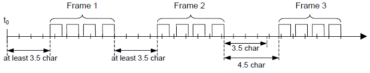
This the interchar interval:

Instead, this is what we get from the serial port when we use a USB adapter:

Which is completely out of specification.
We can deviate from this specification by also accepting these telegrams (provided the content complies with the specifications).
The remaining problem is that it is difficult to determine the end of a telegram, a delay between groups of characters could be due to the driver software. So, we are forced to increase the timeout which tells us when a telegram is complete.
SnapMB uses a different approach. Except in rare cases, we always know how long the expected telegram is, so, the telegram is parsed step by step until its “logical end”, using the same approach that is used with Ethernet protocols.
This allows us to save several milliseconds in the data exchange of the "deterministic" functions. E.g., if we send a request for reading 3 registers, we expect 11 byte as answer.
Have a look at TMBSerBroker::RecvRTUResponse() method into /src/core/mb_serbroker.cpp
In some circumstances, unfortunately, we do not know the size of the incoming telegram in advance, so we have to determine its length via the interframe.
This, for example, is the case of the Device, which acquires all the telegrams transiting on the bus, then discarding those it is not interested in, therefore response telegrams, malformed telegrams, etc.
With reference to the figure, to determine the time interval beyond which we can consider a telegram complete if no other characters arrive, there is the par_InterframeDelay parameter.
This should be at least twice the largest spurious interframe.
To know the largest spurious interframe of the last successfully completed transaction, the GetSerialInterframe() function exists in the Device which also returns, for convenience, the current value of par_InterframeDelay.
USB Serial adapters
I tested several USB/RS485(232) adapters, those with the (original) FTDI chipset are the best, under Linux the driver allows the use of the ASYNC_LOW_LATENCY flag.
Windows, Linux
Nothing to declare, FTDI adapters are recognized out of the box (also in Raspberry OS).
FreeBSD
FTDI driver is separate module, so you will have to load it.\
Add to /boot/loader.conf the line
uftdi_load="YES"
macOS
The adapter is recognized out of the box. Into /dev, You will find two ports for each adapter: tty.* and cu.*, the latter is the correct one to use.
As a second choice there are converters based on the CP2102 chipset, these too are recognized by all operating systems, even if in some cases it is necessary to load the driver.
Finally there is the CH340 chipset, it works quite well and is the cheapest, today this too is in the list of drivers supported by all operating systems.
Installation and commissioning
No installation is required, it is sufficient that in Windows PC snapmb.dll be present in the same folder of your application executable and, in Linux/BSD/Mac OS systems, that libsnapmb.so (or libsnapmb.dylib) is copied to /usr/lib or /usr/local/lib. The system libraries are statically linked to SnapMB, so it doesn't need of any runtime libraries, your programs will can work on "flat" PCs in portable mode, even from USB pendrive.
Usage
As said, some wrappers are provided, this mean that you don’t need to know C++ to use SnapMB. The wrapper is a “glue” code, i.e., a piece of code written in the same language that you are using, which internally interfaces with the library. Currently are provided wrappers for C/C++, C#, Object Pascal (Delphi or FPC/Lazarus) and LabVIEW, which can be compiled 32 or 64 bit, and more could come (if the project has any interest).
Plese refer to Examples and tools and LabVIEW chapters.
Testing SnapModbus
To test SnapModbus I recommend first of all to use the two tools WinBroker and WinDevice putting them in communication with each other.
At startup, by default, both work in TCP on the local address 127.0.0.1 and port 502, so everything will work first time.
It is important to first start the Device and then the Client, otherwise the latter will not find an active Device.
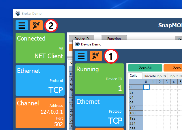
So you can use two different PCs and change the two addresses accordingly.
To test the serial protocol you need of two serial adapters, or, you can use a Virtual Serial Port Driver like this.
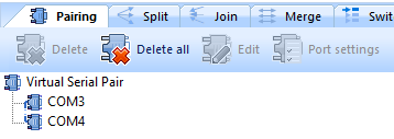
It can create two virtual serial ports connected with a virtual null-modem cable.
Following the figure, you can connect the Client onto COM3 and the Device onto COM4.
Once you are comfortable with the communication, you can open the examples, try them out and modify them for your needs.
Examples and tools
Quick start
C++
#include "snapmb.h"

PSnapMBBroker Client_1;
PSnapMBBroker Client_2;
uint16_t HoldingRegisters[256];

int main(int argc, char* argv[])
{
// Creates 2 Clients the first TCP, the second Serial
    Client_1 = new TSnapMBBroker(ProtoTCP, "127.0.0.1", 502);
    Client_2 = new TSnapMBBroker(FormatRTU, "COM3", 115200, 'N', 8, 1, FlowNONE);

// Reads 16 Holding Registers from the Device N.1 starting from 7000
    Client_1->ReadHoldingRegisters(1, 7000, 16, &HoldingRegisters);
// Write the buffer to the Device N.2 starting from 4000
    Client_2->WriteMultipleRegisters(2, 4000, 16, &HoldingRegisters);

    delete Client_1;
    delete Client_2;
}
C#
using SnapModbus;

    static ushort[] Regs = new ushort[256];
    static SnapMBBroker Client_1;
    static SnapMBBroker Client_2;

static void Main(string[] args)
{
// Creates 2 Clients the first TCP, the second Serial
    Client_1 = new SnapMBBroker(MBConsts.ProtoTCP, "127.0.0.1", 502);
    Client_2 = new SnapMBBroker(MBConsts.FormatRTU, "COM3", 115200, 'N', 8, 1, MBConsts.FlowNONE);

// Reads 16 Holding Registers from the Device N.1 starting from 7000
    Client_1.ReadHoldingRegisters(1, 7000, 16, Regs);
// Write the buffer to the Device N.2 starting from 4000
    Client_2.WriteMultipleRegisters(2, 4000, 16, Regs);
}
Object Pascal (Delphi/Lazarus)
Uses SnapMB;
Var
    Regs : packed array[0..255] of word;
    Client_1 : TSnapMBBroker;
    Client_2 : TSnapMBBroker;
Begin
// Creates 2 Clients the first TCP, the second Serial
    Client_1 := TSnapMBBroker.Create(mbTCP, '127.0.0.1', 502);
    Client_1 := TSnapMBBroker.Create(sfRTU, 'COM3', 115200, 'N', 8, 1, FlowNONE);

// Reads 16 Holding Registers from the Device N.1 starting from 7000
    Client_1.ReadHoldingRegisters(1, 7000, 16, @Regs);
// Write the buffer to the Device N.2 starting from 4000
    Client_2.WriteMultipleRegisters(2, 4000, 16, @Regs);

    Client_1.Free;
    Client_2.Free;
End;
Examples
into /Examples folder you will find many examples to see how to use SnapModbus.
The languages used are C++, C# (Console and WinForm) , Object Pascal (Delphi and Lazarus), you can compile and run C++ examples them into Windows, Linux (all distros), FreeBSD, macOS.
I tested Object Pascal (Lazarus) examples in Windows and Linux, but they should work also into the other OS.
Makefiles and/or project are provided for all of them.
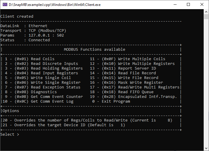


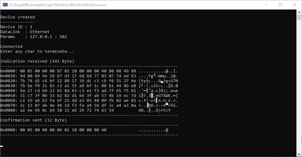
C# WinForm example
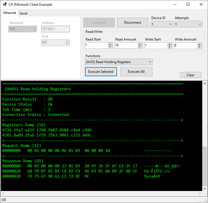
Tools
The tools are big demos that you can study or use whether or not you intend to work with the SnapModbus library.
They are written in Lazarus and the source code is provided.
If you want to rebuild them, you need BGRAControls and BGRABitmaps packages, which can be installed via Online package manager of Lazarus.
WinBroker
Simulates a Broker (Ethernet or Serial), you can do almost everything with it, including the build of custom functions.
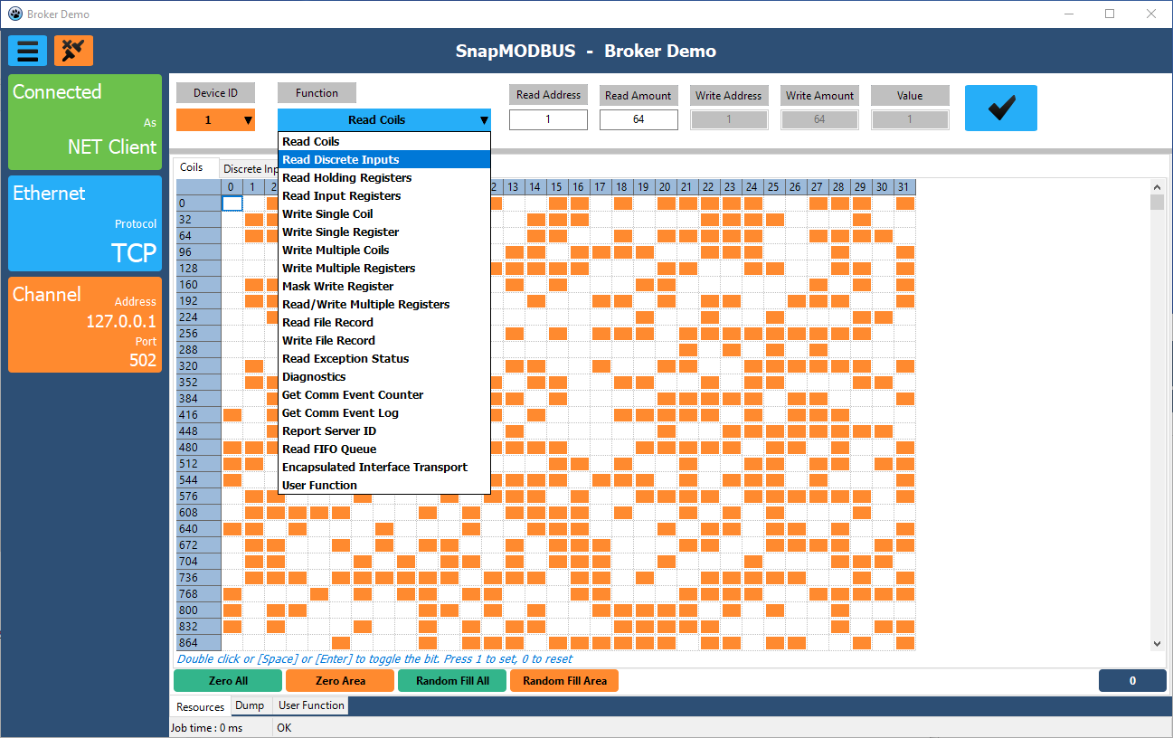
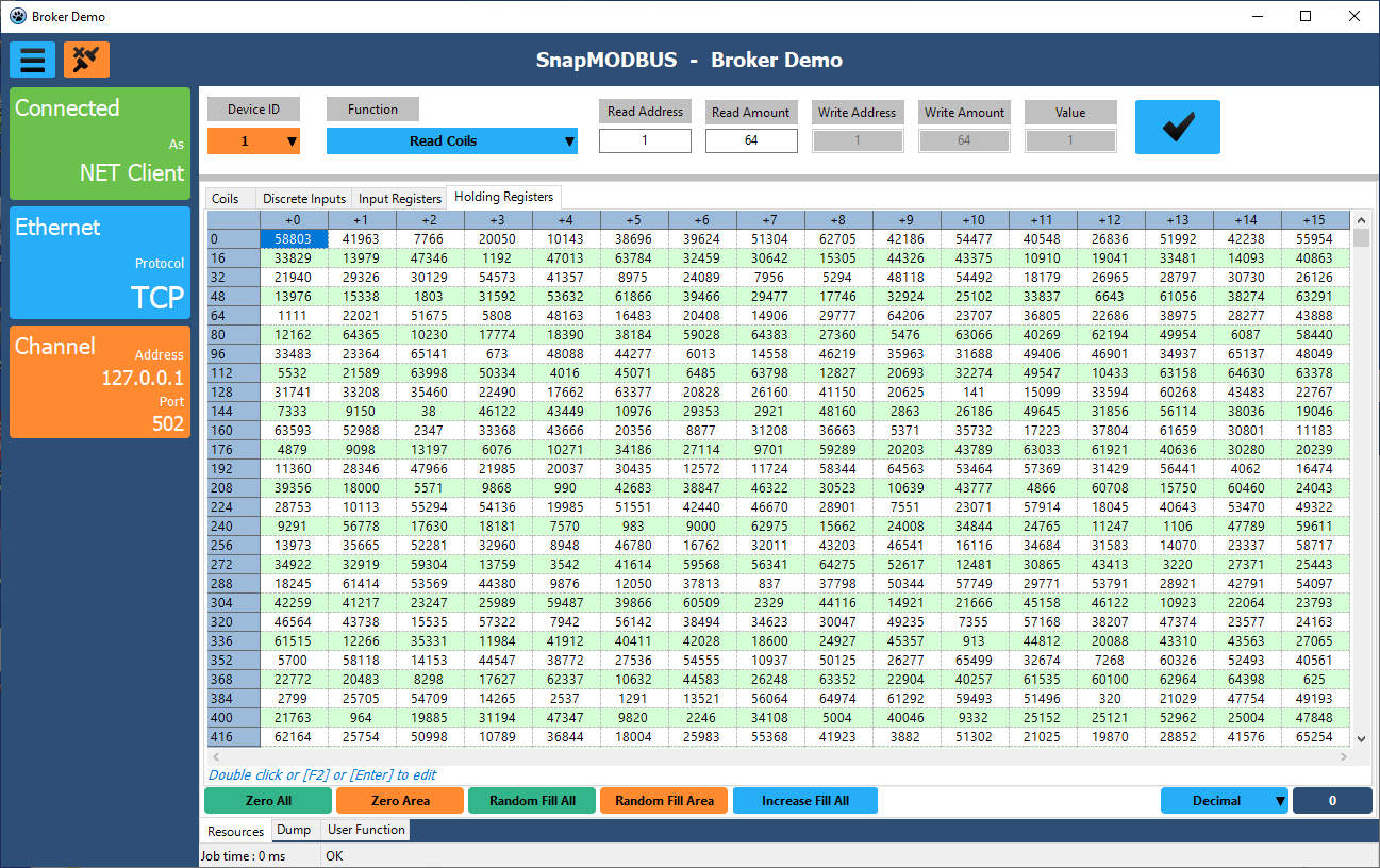
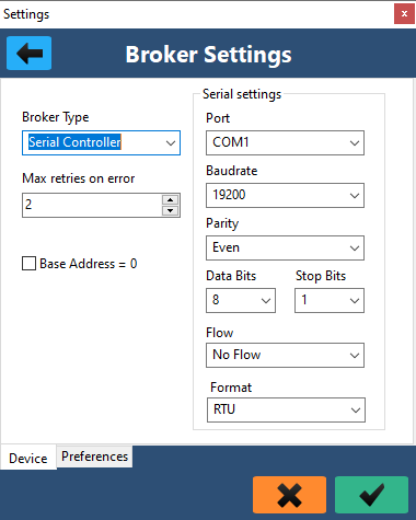
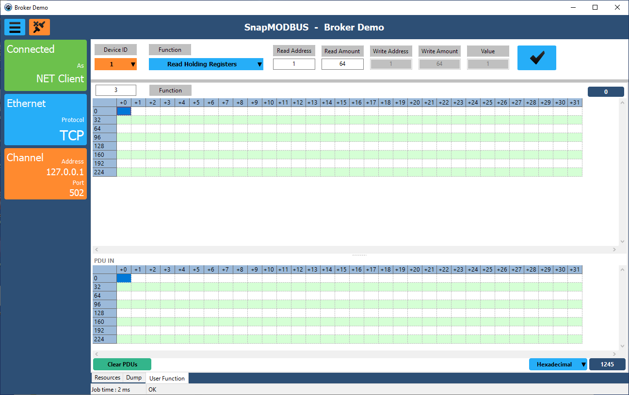
WinDevice
Simulates a Device (Ethernet or Serial).
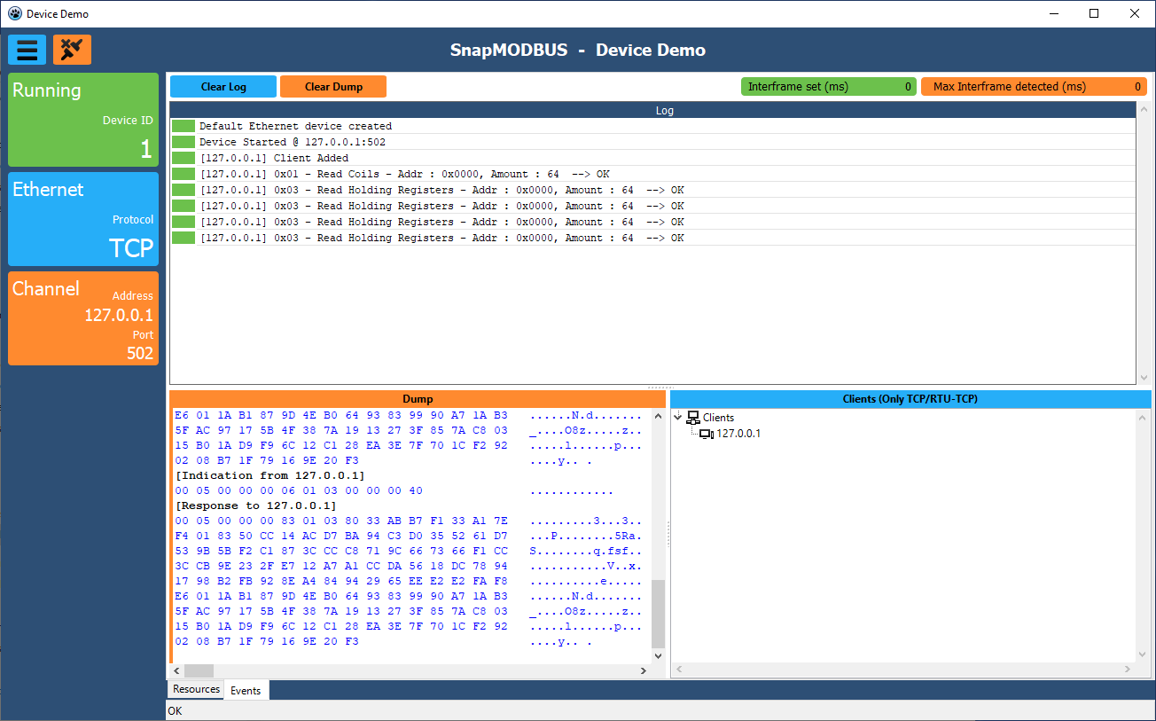
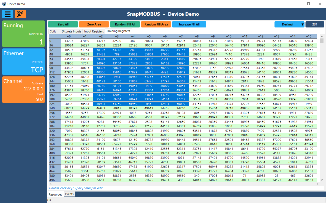
LabVIEW
NI LabVIEW is a software for systems design which uses a graphical language, named "G" (not to be confused with the more pleasant G-point), to build complex laboratory and automation applications.
In a G program, the execution is determined by the structure of a graphical block diagram (the LV-source code) on which the programmer connects different function-nodes by drawing wires. These wires propagate variables and any node can execute as soon as all its input data become available.
LabVIEW offers the same data types/structures as other programming languages, but they are propagated using a different approach.
From this point of view we can consider G as a managed language.
Let’s see how can we interface LabVIEW with SnapModbus, keeping in mind these two major differences (execution and data storage) against the traditional programming languages.
The wrapper provided consists of a series of VI, each of them encapsulates a SnapMB function via the Call Library function node.

Not all SnapMB functions have been wrapped because some of them can't be used (see below) and others are of more sporadic use, the fact remains that you can include them very easily using the VIs you find already written as guidelines.
However, all the functions for data exchange towards Coils, Holding registers, Discrete inputs and Input registers have been implemented, both on the broker and on the device side.
LabVIEW cannot handle the callbacks, i.e. is not possible to call LV pseudo code, from an external binary library.
For this reason, the only way to work with a Device is using the shared resources, for which, the RegisterArea and ReadArea VI are supplied.
Note
All SnapModbus functions are thread-safe, so LabVIEW VI are set to "run in any thread".
under /LabVIEW/Examples/ folder you will find SnapMBExamples.lvproj
which contains the demos and SnapMB.lvlib i.e. the VI library.

Let's see some examples with their diagrams. To run them, if you don't have real hardware ready, you can use WinBroker and WinDevice tools.
ClientDemo
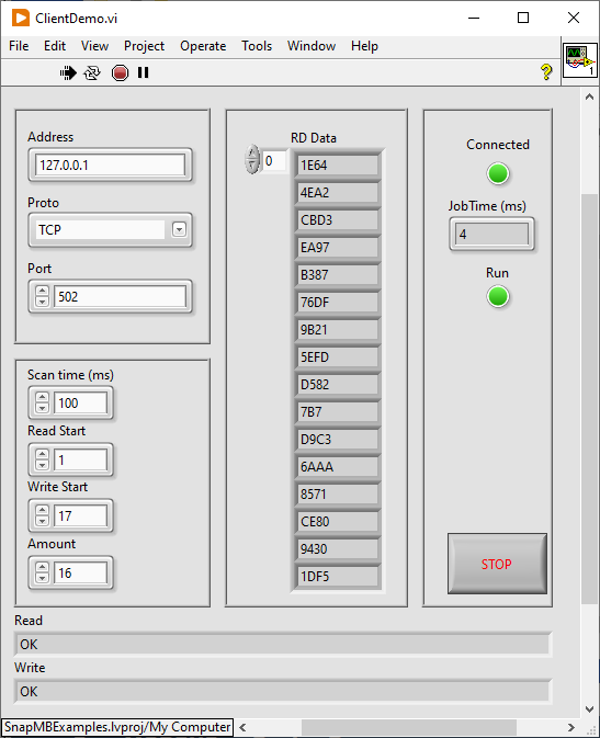
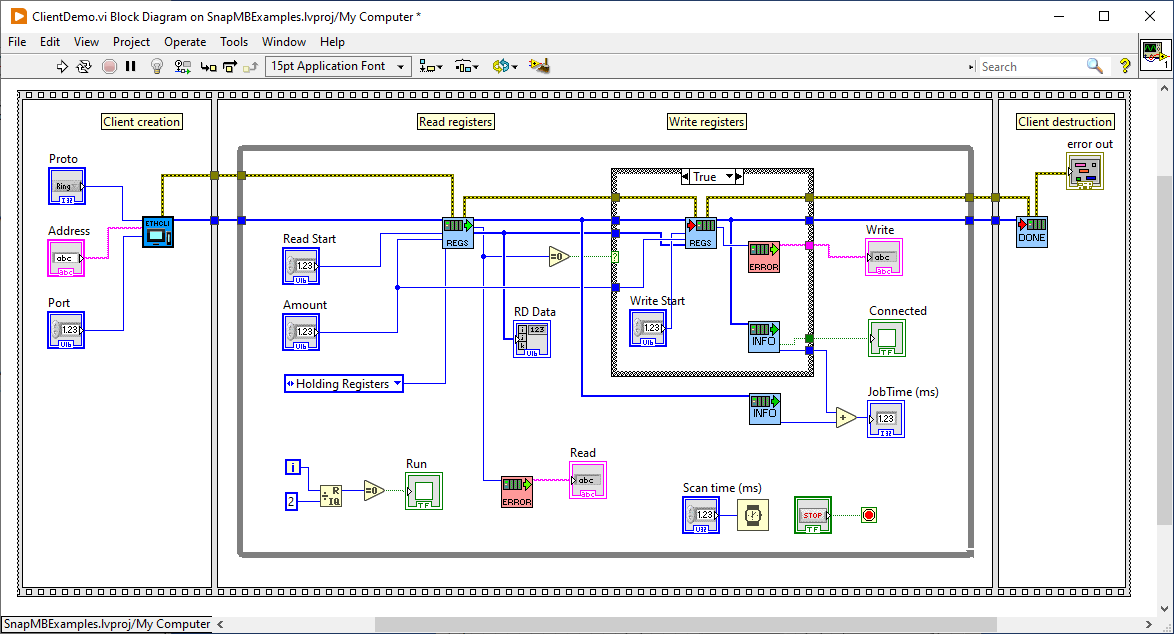
ClientSerial
Same as above, but using a Serial Client.
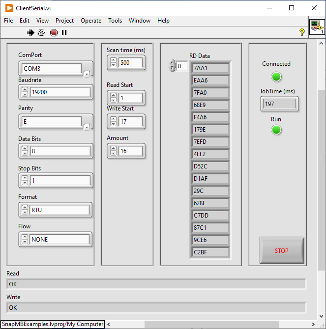
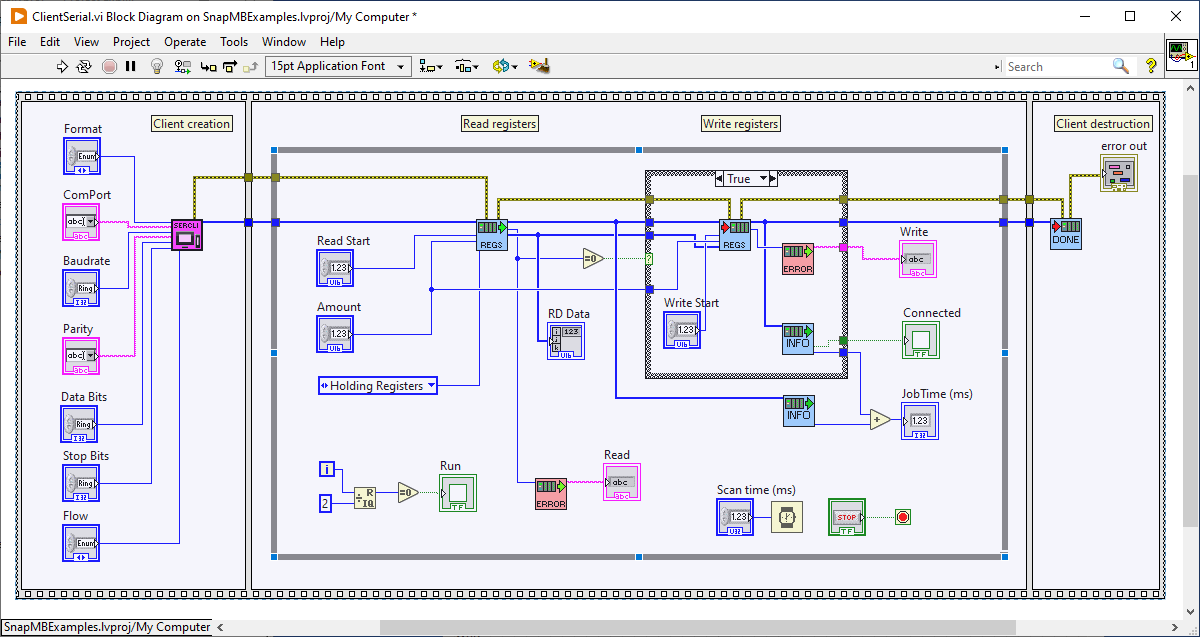
FieldControllerDemo
Two Devices are added, the first Ethernet and the second Serial, look at FieldController usage for more info.
The program read some registers from the first device and write them to the second.
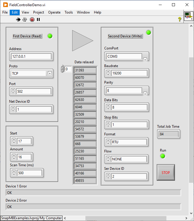
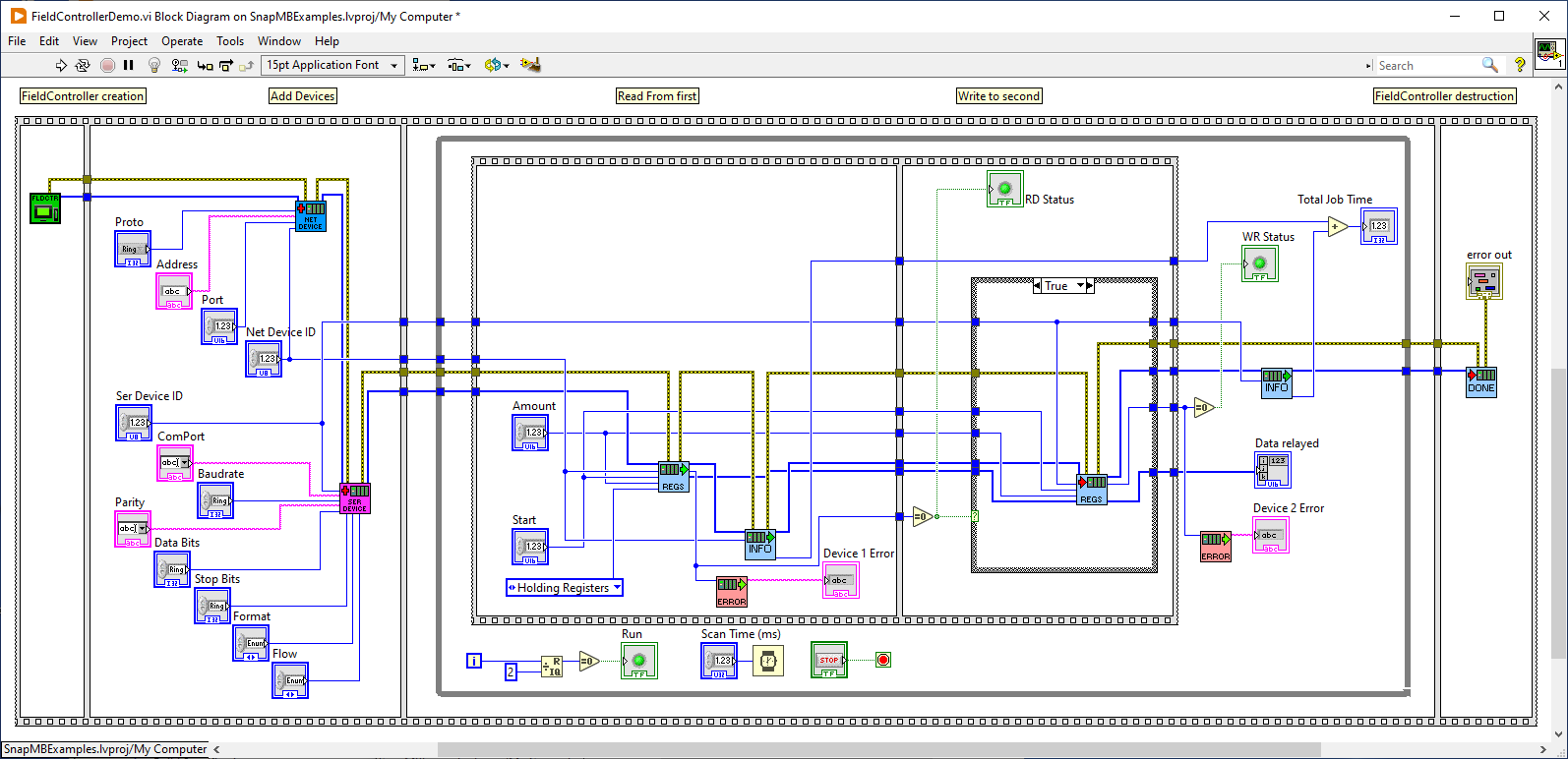
DeviceDemo
A simple Device which shares the resources and uses ReadArea to access them safely (see Concurrency)
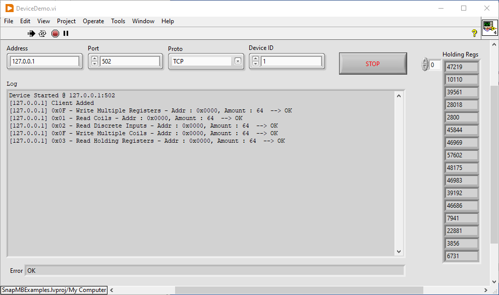
I have divided the diagram into two parts for better readability.
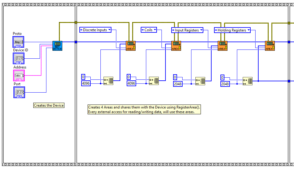 Part 1
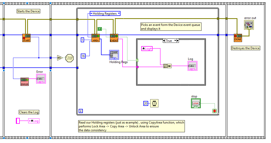 part 2
Rebuild SnapModbus
SnapModbus is written in "flat" C++, i.e., without dependencies. There is a snap_platform.h file with some "definitions" to adjust the included files, but all sources are the same for all operating systems and platforms.
Windows
Visual Studio Community Edition
Into
/build/windows/VisualStudio
you will find snapmb.sln, just open it. It should be compatible also with preceding versions.

MinGW
Go to
/build/windows/mingw
and run build32 or build64,
a pause statement will allow to see the compilation result also if you run them by double-clicking in explorer.
I used TDM-GCC, you can download it from https://jmeubank.github.io/tdm-gcc/
Maybe you need to modify the batch files, specify the installation path and the release, currently I installed the release 10.3.0 in C:
The libraries will be generated into \build\bin\mingw32 or \build\bin\mingw64
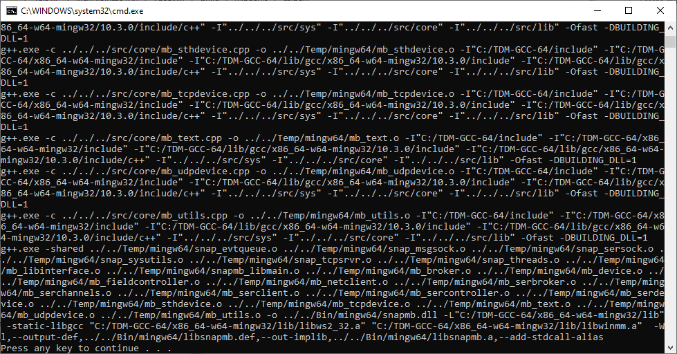
Linux (All distros)
Go to
/build/linux
and run
sudo make install
libsnapmb.so by default will be copied into /usr/lib, to change this path you can set the LibInstall variable,
e.g.
sudo make install LibInstall=<MyPath>
Some 64 bit distributions (CentOS and Red Hat) need libsnapmb.so into /usr/lib64 instead of /usr/lib So you should use
LibInstall=/usr/lib64
FreeBSD
Go to
/build/bsd
and run
sudo gmake install
in FreeBSD gcc is a port, so the compiler present will be g++[version index], by default (I used FreeBSD 13.1) the variable Compiler is set to g++11, if you have a different version, you can choose one of these options:
- Change the variable
Compilerinto the makefile - Run
sudo gmake install Compiler=g++[YourVersion] - Create a symbolic link into /bin
g++-->g++[YourVersion]
macOS
Open a terminal and type
g++
if the compiler is not installed will appear a window asking for install it, confirm.
Then, go to into
/build/macOS
and run
sudo make install
By default will be generated libsnapmb.dylib unless you change the variable LibExt
e.g.:
sudo make install LibExt=so
Stress tests
When working on industrial plants, the equipment often remains on and running for long periods, so it is essential that the software involved is reliable.
It is important to use test methods that go beyond the usual work/fail method, which is only useful in debugging.
Two types of stress-tests were performed on SnapModbus.
- Concurrency
- Error Memory Check
Note
In the distribution there are also the sources of the stress tests, so, if you want, you can reproduce or modify the tests according to your needs.
Concurrency test
With this test we verify the lock/unlock mechanisms of the memory areas (see here).
SnapModbus is very flexible, and allows heavy use of multithreading, allowing multiple objects to work simultaneously.
Therefore, it is important that, even in harsh conditions, it never happens that the data is corrupted, or that it is partially read, due to simultaneous accesses from multiple objects.
This is the principle scheme used.
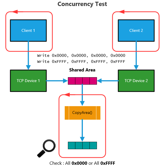
An area of four registers is shared between two Devices working simultaneously on two different ports and our application.
Two Clients running in two independent applications are connected to the two Devices and both write alternately in the registers two patterns:
- 0x0000, 0x0000, 0x0000, 0x0000
- 0xFFFF, 0xFFFF, 0xFFFF, 0xFFFF
The application continuously reads the four registers, using the safe function CopyArea(), and checks that they always contain a single pattern ie all four are 0x0000 or 0xFFFF.
If the lock/unlock management doesn't work, the data occasionally gets partially overwritten, because the writing of the values is not atomic and can be interrupted by another thread.
This was the result.
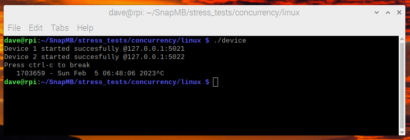
1.703.659 checks were made without errors.
Error memory check
With this test we verify that there are no memory errors and that our library does not have memory leaks or that it does not "eat" memory in the long run.
For this test I used Valgrind, a program which allows both to intercept memory errors and to keep track of block allocations/de-allocations, verifying that they are consistent.
This is the principle scheme used.
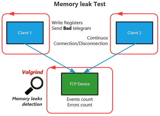
There are two clients working the two different threads connected to our Device at the same time.
The first client writes to registers continuously, and occasionally sends bad telegrams. The second Client connects and disconnects continuously.
With the first client we test the ability to handle critical situations and, above all, that these do not cause errors in the memory.
With the second client we test that the continuous connections/disconnections, which in the Device cause the creation/destruction of many socket-threads, are correctly managed without memory leaks.
Our program, which runs inside Valgrind, counts the total events and error handling encountered due to bad telegrams received from Client 1.
This was the result.

- 2.443.996 Events detected
- 71.848 Errors succesfully handled
- 1.402.912 Memory blocks correctly allocaded and deallocated
- 1.536.876.890 byte of memory managed during the run
- 0 memory errors detected by Valgrind
References
- Brief but complete description of the protocol in its various forms (Wikipedia)
- Modbus organization
- Official specifications
License
SnapModbus is distributed as a binary shared library with full source code under GNU Library or Lesser General Public License version 3.0 (LGPLv3)
Basically this means that you can distribute your commercial software linked with SnapModbus without the requirement to distribute the source code of your application and without the requirement that your application be itself distributed under LGPL.
A small mention to the project or the author is however appreciated if you include it in your applications.
SnapModbus examples, including wrappers and demos, are not covered by any license, thus they are completely free.
Disclaimer of Warranty
THERE IS NO WARRANTY FOR THE PROGRAM, TO THE EXTENT PERMITTED BY APPLICABLE LAW. EXCEPT WHEN OTHERWISE STATED IN WRITING THE COPYRIGHT HOLDERS AND/OR OTHER PARTIES PROVIDE THE PROGRAM "AS IS" WITHOUT WARRANTY OF ANY KIND, EITHER EXPRESSED OR IMPLIED, INCLUDING, BUT NOT LIMITED TO, THE IMPLIED WARRANTIES OF MERCHANTABILITY AND FITNESS FOR A PARTICULAR PURPOSE. THE ENTIRE RISK AS TO THE QUALITY AND PERFORMANCE OF THE PROGRAM IS WITH YOU. SHOULD THE PROGRAM PROVE DEFECTIVE, YOU ASSUME THE COST OF ALL NECESSARY SERVICING, REPAIR OR CORRECTION.